Posted: Wed Jul 09, 2014 11:15 am Post subject:
Pimp my squarewave Subject description: because squarewaves can be boring
Working mostly with digital circuits in my Lunetta experiments, I sometimes wish for some beefier sound than that of the typical squarewaves. Of course, I could start adding filters to make the resulting sound a bit more interesting. Here is an attempt to do it the digital way. It extracts harmonic frequencies from the original signal and adds them together again.
What the circuit does is extracting the rising and falling edges of the input signal (a squarewave) using the two RC pulse generators and combining the pulses to the doubled input frequency. That one is then divided by three using a Johnson counter. The original frequency is also divided by three. Then it adds the original frequency, the frequency*2/3, the frequency*2 and the frequency/3 together for the output signal. The ratio 2:3 is that of the equal tempered perfect fifth and the ratio 1:2 is the octave. So no matter what the input frequency is, the output frequencies will be harmonic.
Because of the 10 nF condensators used, the output waveform looks rather symmetric in a range from 300...1500 Hz. Above that the pulses become too long and the waveform starts to degenerate. Using 1nF condensators instead moves that point to about 5 KHz. Anyhow, that's not a problem. You will note that only if you sweep through the frequency range. One interesting effect is when you sweep above that point and then down again. The generated waveform will suddenly look different, but sound similar. This is because the two Johnson counters get out of sync. Again, not a problem, but interesting to note.
The result is a somewhat more interesting sound than that of the original squarewave. In the current circuit the frequencies are mixed using the same resistor values. Using pots instead would allow to attenuate individual frequencies in the output signal and by that change the color of the sound somewhat. Soundfiles to follow soon.
Ultimatively I am looking for a circuit that changes my input frequency, but only slightly. So I could add it to the original signal and get those beautiful interferences. Haven't been successful with my experiments in that direction yet. Any suggestions are welcome.
SquarewaveHarmonizer.PNG
Description:
Filesize:
34.25 KB
Viewed:
676 Time(s)
This image has been reduced to fit the page. Click on it to enlarge.
Pictures:
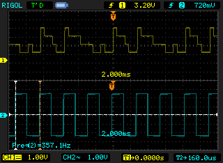
(1) the input square wave (below) and the generated output waveform
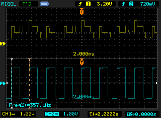
(2) above 2KHz the peaks of the output waveform start to fall together
(3) after sweeping down again, a slightly different waveform is generated
Sound file:
(1) the input squarewave (about 360 Hz)
(2) the four frequencies (120, 240, 360, 720 Hz)
(3) all four mixed together
(4) sweeping up and down again
For this I changed one of the dividers from a /3 to a /5 by connecting 4093 pin1 to 4015 pin2 instead of pin12. Still a harmony, but more interesting in the resulting mix.
Nice! When you keep posting gems like this I'm starting to get very excited every time I see your screen name.
As to changing the input frequency only slightly, have you tried phase locked loops? Look into the 4046. You could try something like multiplying the frequency by 5 then dividing it by 4? Or by 9 then 8?
Yes, I was thinking about the 4046 and placing a divider in the feedback loop to make it a multiplier. That would give a new frequency close to the original one. Something I will try as soon as I am done with my Lunetta-Lab board. However, even a 9:8 ratio will result in a fixed frequency, and this will result in a fixed beat frequency for the interference. It would be nice to have this beat frequency actually changing slowly.
Right now I am looking in dynamically changing the divider ratios to see if that adds a nice flavor to the sound. Stay tuned.
Joined: Jan 14, 2010 Posts: 5599 Location: Moon Base
Audio files: 705
Posted: Fri Jul 11, 2014 10:02 am Post subject:
synaesthesia wrote:
Yes, I was thinking about the 4046 and placing a divider in the feedback loop to make it a multiplier. That would give a new frequency close to the original one. Something I will try as soon as I am done with my Lunetta-Lab board. However, even a 9:8 ratio will result in a fixed frequency, and this will result in a fixed beat frequency for the interference. It would be nice to have this beat frequency actually changing slowly.
Thanks commathe and PHOBoS. I definitely will try a 4046 later.
I guess my current experiment is just for the records. I added a 4052 as a sequencer to step through 4 combinations of 2 frequencies and clocked it by the input frequency/8. The chopper effect dominates and there is no such thing as a beat frequency. Not worth posting. However, when clocked with 20 Hz a nice arpeggio of those 4 tones is generated. That could be useful at some time.
Posted: Fri Jul 11, 2014 4:51 pm Post subject:
Re: Pimp my squarewave Subject description: because squarewaves can be boring
synaesthesia wrote:
Ultimatively I am looking for a circuit that changes my input frequency, but only slightly. So I could add it to the original signal and get those beautiful interferences. Haven't been successful with my experiments in that direction yet. Any suggestions are welcome.
Variable delays and then mix? It is not so hard to get some lag on squares, but it will have a workable frequency range too ... not sure if you could get enough delay that way easily _________________ Jan
also .. could someone please turn down the thermostat a bit.
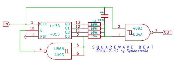
Okay, this one is a bit better. It delays the falling or rising edge of the input squarewave via an RC network. R would normally go to Vdd or GND, but it goes to a resistor network connected to the outputs of a 4-bit Johnson counter instead. The changing voltage at that point varies both the delayed edge and the delay. The beat frequency is f/8 then, which is pretty fast. Sound file is attached. The first few seconds with the input squarewave, then the output signal while sweeping the input frequency up and down.
There are a few variations possible. You could add an inverter and build separate delays for the falling and rising edges. Tried that and it wasn't much better. You could also use the second half of the 4520 to build another Johnson counter and divide the input frequency down by 8 before it shifts the counter with the resistor network. Gives you a beat frequency of f/64. But that was a bit too slow. Simpler is better, I prefer the first version.
SquarewaveBeat.png
Description:
Filesize:
15.91 KB
Viewed:
539 Time(s)
This image has been reduced to fit the page. Click on it to enlarge.
Still messing around with the idea to turn a simple square wave into something more interesting. I wondered what happens if you divide the original frequency by two for three times and then combine the three divided frequencies again? If you keep the order and use the weights 1,2,4 you should get a staircase ramp with 1/8 the original frequency. Ok, what happens if you recombine them with other weights? You should get other stepped waveforms.
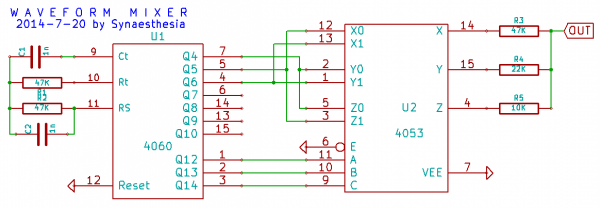
I wanted to know how these sound and put together the following small circuit. It uses the 4060 to generate a high frequency that is then divided down. The first three divider output stages are fed through a 4053 which combines them again via three resistors with ratios 1:2:4. The 4053 changes the order of the first three frequencies controlled by the last three divider outputs of the 4060.
The generated waveforms should look similar to the waveforms in the image below. The image was actually generated using a spreadsheet and has smoothed lines. The real waveforms will repeat for much longer and will look like staircases. Each waveform has the same period, but the dominant frequency changes depending on how the divided frequencies are recombined.
WaveformMixer.PNG
Description:
Filesize:
22.21 KB
Viewed:
631 Time(s)
This image has been reduced to fit the page. Click on it to enlarge.
Waveforms.PNG
Description:
Filesize:
47.13 KB
Viewed:
430 Time(s)
This image has been reduced to fit the page. Click on it to enlarge.
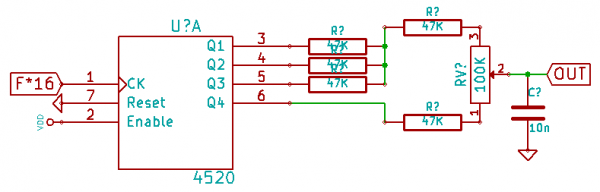
The following circuits needs the original frequency multiplied by 16 as an input. This could be done using a 4046 PLL. However, I am still experimenting with the 4046 to find out how to connect it to ensure that it locks fast enough. So for this test I simply used a 16 times higher input frequency.
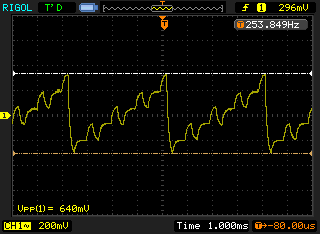
The counter divides the input frequency by 2,4,8,16 and mixes the outputs through a resistor network. The pot can be used to select between an output close to a square wave (1:left), an output almost close to a ramp (3:middle), and an output with many overtones (5:right). The resistors are chosen to keep the volume at the same level, as far as this is possible. There still is a noticeable drop in volume when the pot goes through the middle position (3). The small capacitor at the output filters the resulting wave form a bit and can be left out.
WaveformBlender.PNG
Description:
Filesize:
9.27 KB
Viewed:
361 Time(s)
This image has been reduced to fit the page. Click on it to enlarge.
Here is a small circuit snippet that I plan to use for a kind of PWM effect when a tone is triggered in my next semi-modular Lunetta. The idea is to turn a square wave into a pulse wave with a varying pulse length. I am using a 4049 because it can drive higher loads, and because I have so many of them. I believe that other inverters should work as well, but I haven't tried that yet.
The circuit works best with square waves that have about 50% duty cycle and a rather low frequency, approximately 100 to 1000 Hz, but other audio signals could be used as well. The first inverter U1D after the input turns the audio signal into a waveform with steep edges. After that a small capacitor plus an LDR create pulses with increasing length. The trigger input signal is used to generate a brief pulse when the tone starts using Inverter U1F that lights the LDR with the LED. You could either use a signal from a keyboard or a clock from your circuit for the trigger.
I am using a DIY vactrol made from a GL5539 and a bright LED. The values are not critical, but you need to make sure that the package is absolutely light-tight. During the recovery time of the LDR the resistance slowly increases from the minimum value back to the dark resistance. Unfortunately that means that you cannot change the duration of the effect because it completely depends on the LDR recovery time. But you can change the small cap in the input path. I found values from 1n to 10n working best. If the input signal frequency is too high, the effect becomes weaker because the variation of the pulse width becomes less noticeable.
Let me know what you think, or how this can be improved. My audio recording cable is broken, so I post a video of the circuit in action this time.
Edit: Video size trimmed, MP3 added (no idea why my browser thinks the video is corrupt, the downloaded file works fine)
PWM Effect.PNG
Description:
Filesize:
18.4 KB
Viewed:
344 Time(s)
This image has been reduced to fit the page. Click on it to enlarge.
One simple change: adding a 100K resistor in series with the LDR makes striking a tone less squeaky, but still preserves the PWM effect. Also, 4.7nF works much better for C1.
Joined: Feb 18, 2013 Posts: 150 Location: south Germaica (schwabilon)
Posted: Sat Jan 10, 2015 3:24 am Post subject:
when iam using recordings of my sirens in my daw .... i figured out that using a simple haas effect on that channel make the Squrewaves sounding real rich ....
http://en.wikipedia.org/wiki/Precedence_effect
the haas ist simple a delayed (~3ms+) copy paned to the other side. so it must be simple to feed a Squrewave in a long Shiftregister (feed with a fast clock) grab a signal on the first out and the 2nd signal on the last step. connect 2 of this Squrewave "upnicer" from this thread to the 2 signals and panned one to the left and the other to the right must be the killer FX....
Joined: Jan 14, 2010 Posts: 5599 Location: Moon Base
Audio files: 705
Posted: Sat Jan 10, 2015 5:03 am Post subject:
DUBmatze wrote:
when iam using recordings of my sirens in my daw .... i figured out that using a simple haas effect on that channel make the Squrewaves sounding real rich ....
http://en.wikipedia.org/wiki/Precedence_effect
Joined: Feb 18, 2013 Posts: 150 Location: south Germaica (schwabilon)
Posted: Sat Jan 10, 2015 8:39 am Post subject:
PHOBoS wrote:
I didn't know there was a name for it but I do the same thing to turn mono into stereo sounds.
as for delay with a shiftregister have a look at this.
LOL ... there is nothing in electronics you can do what Phobos not have done b4 ...
when bender read "old robot porn" in futurama - this is phobos stuff ... with a bit synaesthesia and things from the other Lunetta ppl here .....
totally OT but this is the stuff iam playing atm with:
iam using the Haas thing on mono on stereo on evrything .... the cool thing is he is total monocompatible (not like the other voodoo with change phase or so ...) so if you play your music on a soundsystem, in a club or an old kitchen radio - Haas is your friend
.. shit i got it on 11/28 chanels ....
(sound like this: https://soundcloud.com/matze-dub/vst-audio-damage-dubstation-vs-valhalla-freq-echo)
/OT end ....
haas.png
Description:
Filesize:
132.83 KB
Viewed:
333 Time(s)
This image has been reduced to fit the page. Click on it to enlarge.
A discussion of a similar circuit using a 4049 spawned the idea to use a separate voltage to control the threshold level of the inverter gate for PWM modulation. I experimented a bit and came up with the following circuit. It creates a PWM effect as well, but this time varies the response with a voltage from a triangle oscillator. The result is a nice cyclic change in the timbre of the output.
U1D,E,F is a low frequency triangle oscillator using 4049UBE gates. The incoming square wave is fed to inverters via a cap. The triangle wave is connected to the other end of the cap to shift the threshold level for each inverter. Because the effect is extremely frequency dependent, I tripled the modulation stage with different cap values and mixed the results of U1A,B,C via resistors. This way, the circuit handles an input frequency range from about 100 to 1200 Hz. The modulation frequency can be modified by a pot. I personally prefer a rather low modulation frequency, because it otherwise tends to sound more like a tremolo and the PWM effect becomes secondary.
The recording demonstrates the circuit with a few frequencies between 130Hz and 800Hz and a middle setting for the modulation speed. Sorry for the noise on the video which is pretty apparent during the low frequencies at the beginning. It comes from the fan in the DSO.
Edit 1/12: schematic updated (values of R1,R5)
ButterflyEffect.PNG
Description:
Filesize:
25.47 KB
Viewed:
369 Time(s)
This image has been reduced to fit the page. Click on it to enlarge.
Taking the idea from the Waveform Blender a step further, I first simplified the resistor values for the blender pot a bit (small schematic) and then changed the normal pot to a digitally controlled pot (in the larger schematic). A 4051 is connected to a series of resistors and the selection input is used to switch between the eight possible tap points. The goal was to change the waveform of a tone while it is playing and to achieve something similar to a filter sweep from high-pass to low-pass.
Also in the larger schematic, you find a tone generator with variable divider. This is similar to the 16-step divider circuit. The output goes to a counter that connects to the three digi-pot inputs. A 4040 is used to generate the timing for the selection inputs for the digi-pot (Q0..Q2) as well as the divider setting (Q3..Q5) for the tone frequency. In the schematic I omitted the inverters for the outputs in order to get an ascending sequence. For the modulation, each tone needs to go through the eight digi-pot steps while it is playing. The result is a waveform that changes in eight steps from a jagged waveform with many overtones to a simple stepped ramp-like waveform.
The idea works, but the hardware implementation is not very practical and can hardly beat a real filter. However, it might be useful when implemented in software.
Mind that there is no envelope generator in the circuit. The attenuation comes entirely from the frequency spectrum (see FFT graph in the video).
Waveform Blender2.PNG
Description:
Filesize:
7.38 KB
Viewed:
306 Time(s)
This image has been reduced to fit the page. Click on it to enlarge.
Waveform Modulation.PNG
Description:
Filesize:
39.98 KB
Viewed:
357 Time(s)
This image has been reduced to fit the page. Click on it to enlarge.
Finally I succeeded in creating a circuit that creates the sound that I was looking for for so long. I find the interference of two very close frequencies fascinating and wanted to have a controllable oscillator that creates that sound without the need for manual re-adjustment when changing the frequency. After many failed attempts to create this using dividers or a PLL, I took another fresh look at this with the current controlled oscillator in mind that I posted in another thread. The advantage of that circuit is that it only uses a single Schmitt-Trigger inverter like the 4016 and that you have a simple frequency control via an input resistor that can be applied to two oscillators at once. Starting there I found that what really matters is that you make sure that the mixing does not interfere with the oscillators. I tried mixing them with diodes and gates. An XOR or AND/NAND gate works best, but even a simple diode/resistor gate will do the trick.
Here is how this circuit works: there are two oscillators that are fed with the same current over a resistor network. You could use some other means here as well to control the current, like a pot or an LDR. The current is used to load the capacitor at the input of each oscillator. When the voltage reaches the trigger level for one inverter, the corresponding capacitor is discharged via the feedback path in a brief pulse. So both oscillators generate a pulse waveform that is high most of the time and shows brief low pulses on the scope. I have added a resistor in the feedback path to make those pulses a bit wider. To mix those two outputs, a simple diode network can be used. Only the negative pulses will go through, so I added a pull-up resistor. That gives you an output signal that is low whenever one of the inverters is at a low level and high otherwise. To smoothen the waveform a bit, a small capacitor to ground is finally added.
The circuit needs initial tuning to compensate for the slight variations of the resistor and capacitor values. For that a pot is used that distributes the current to the two oscillators. I found that it works best with a pot of about 100K or higher. The control characteristic is symmetrical then and the sweet spot will be somewhere in the middle of the pot range. To make better use of the pot range a resistor with about half of the value of the pot is added to one leg. That will allow you to adjust the ratio so that you get the same frequency from both oscillators, as well as one of them running at twice or even three times the frequency of the other. Keep the input constant and tune to the sound you like best. After that the oscillators will roughly stay in that ratio over a good part of the audible range. This is not precise at all, and you will notice the beat frequency changing, but I found it working surprisingly good.
In the recording I first use the resistor network driven by a counter to demonstrate a range of 16 tones. Then I start changing the balance pot at the input to demonstrate the range of sounds from the dual oscillator. A 40106 has four inverters left, so you could also create four low frequency oscillators and connect those to the four resistors to get an instant melody generator with a cool sound. Enjoy!
Double DCO.PNG
Description:
Filesize:
20.67 KB
Viewed:
302 Time(s)
This image has been reduced to fit the page. Click on it to enlarge.
You cannot post new topics in this forum You cannot reply to topics in this forum You cannot edit your posts in this forum You cannot delete your posts in this forum You cannot vote in polls in this forum You cannot attach files in this forum You can download files in this forum

 Forum index » DIY Hardware and Software » Lunettas - circuits inspired by Stanley Lunetta