| Author |
Message |
numbertalk

Joined: May 05, 2008
Posts: 992
Location: Austin, TX
Audio files: 5
|
 Posted: Mon Jan 19, 2009 8:06 am Post subject: Posted: Mon Jan 19, 2009 8:06 am Post subject:
|
  |
|
| AndyR1960 wrote: | | VCO 2 provides the sync signal, and as shown on my layout, sync occurs when the switch toggle is down. In the "up" position the sync input to VCO 1 is tied to -15v via a 100k resistor, which prevents any spurious re-triggering. |
So if VCO 2 provides the sync signal then VCO 2 is the master osc and VCO 1 is the one that resets, the slave osc, right? |
|
|
Back to top
|
|
 |
Broadwave

Joined: Feb 16, 2007
Posts: 347
Location: Manchester UK
Audio files: 6
|
| Posted: Mon Jan 19, 2009 8:29 am Post subject:
|
|
|
| numbertalk wrote: |
So if VCO 2 provides the sync signal then VCO 2 is the master osc and VCO 1 is the one that resets, the slave osc, right? |
Yes, that's right 
_________________
Kronos 2-88, Kronos 61, Studiologic Sledge V2/SL, Broadwave ARP 2600EX, Broadwave 18U ARP based Eurorack Modular, Broadwave Minimoog Clone, GEM S2 Turbo.
Synth DIY Projects
Musical Doodlings |
|
|
Back to top
|
|
|
numbertalk
Joined: May 05, 2008
Posts: 992
Location: Austin, TX
Audio files: 5
|
| Posted: Mon Jan 19, 2009 9:13 am Post subject:
|
|
|
| AndyR1960 wrote: | | numbertalk wrote: |
So if VCO 2 provides the sync signal then VCO 2 is the master osc and VCO 1 is the one that resets, the slave osc, right? |
Yes, that's right |
Thanks  |
|
|
Back to top
|
|
|
funkyfarm

Joined: Jan 21, 2007
Posts: 583
Location: France
Audio files: 3
|
| Posted: Fri Jan 23, 2009 10:08 am Post subject:
|
|
|
mki...mkiii...  |
|
|
Back to top
|
|
|
LetterBeacon
Joined: Mar 18, 2008
Posts: 454
Location: London, UK
|
| Posted: Sun Feb 01, 2009 11:43 am Post subject:
|
|
|
| numbertalk wrote: | Here's a MOTM style panel I've made. It's huge.
EDIT - I'm not so great with photo software and can't export from FPD, so I'm just attaching the FPD file. |
Nice looking panel!
One thing I'm not clear about, and it's very definitely me being a bit dumb, but is the hole in the bottom right hand corner a trigger input? |
|
|
Back to top
|
|
|
e-grad
Joined: Sep 12, 2008
Posts: 142
Location: Berlin
|
| Posted: Sun Feb 01, 2009 4:09 pm Post subject:
|
|
|
| It should be triangle out!? |
|
|
Back to top
|
|
|
numbertalk
Joined: May 05, 2008
Posts: 992
Location: Austin, TX
Audio files: 5
|
| Posted: Sun Feb 01, 2009 4:35 pm Post subject:
|
|
|
Thanks!
It's a Triangle wave output. I'm adding a sine & triangle out for LFO use:
http://www.electro-music.com/forum/topic-30667.html#224604
| LetterBeacon wrote: | | numbertalk wrote: | Here's a MOTM style panel I've made. It's huge.
EDIT - I'm not so great with photo software and can't export from FPD, so I'm just attaching the FPD file. |
Nice looking panel!
One thing I'm not clear about, and it's very definitely me being a bit dumb, but is the hole in the bottom right hand corner a trigger input? |
|
|
|
Back to top
|
|
|
numbertalk
Joined: May 05, 2008
Posts: 992
Location: Austin, TX
Audio files: 5
|
| Posted: Fri Feb 06, 2009 12:12 pm Post subject:
|
|
|
Hi Andy,
The docs you posted specify that the Manual PW pot is wired as a voltage divider between 0V & -15V - I just wanted to verify how to correctly wire this to the pot - would -15V go to the CCW lug and ground to the CW lug or vice-versa?
Thanks! |
|
|
Back to top
|
|
|
Broadwave
Joined: Feb 16, 2007
Posts: 347
Location: Manchester UK
Audio files: 6
|
| Posted: Sat Feb 07, 2009 10:20 am Post subject:
|
|
|
| numbertalk wrote: | | I just wanted to verify how to correctly wire this to the pot - would -15V go to the CCW lug and ground to the CW lug or vice-versa? |
Hi Numbertalk,
Ground (0V) goes to the CCW lug, and -15V to CW.
Cheers.
_________________
Kronos 2-88, Kronos 61, Studiologic Sledge V2/SL, Broadwave ARP 2600EX, Broadwave 18U ARP based Eurorack Modular, Broadwave Minimoog Clone, GEM S2 Turbo.
Synth DIY Projects
Musical Doodlings |
|
|
Back to top
|
|
|
numbertalk
Joined: May 05, 2008
Posts: 992
Location: Austin, TX
Audio files: 5
|
| Posted: Sun Feb 08, 2009 7:35 pm Post subject:
|
|
|
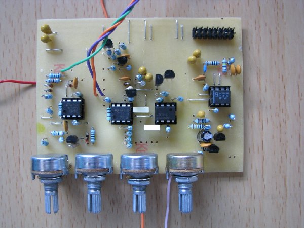
Thanks Andy!
Finished wiring up and trimming my board tonight and it all works! Need to etch and wire up the saw-to-tri converter and get brackets in an order I'm waiting on from Bridechamber then I can mount it in my synth! Here are a couple photos - the wiring is a total rat's nest at the moment.
I'm at my upload max so photos linked from Flickr.

 |
|
|
Back to top
|
|
|
ericcoleridge

Joined: Jan 16, 2007
Posts: 889
Location: NYC
|
| Posted: Mon Feb 09, 2009 2:59 am Post subject:
|
|
|
| numbertalk wrote: |
Finished wiring up and trimming my board tonight and it all works! |
Paul,
Beautiful job man! It looks fantastic.
I really love this VCO, definitely my favorite sounding of all osc. I've built so far (MFOS, CGS, EFM). How do you like yours?
Thanks for posting this pic, really inspiring me to get mine paneled up! |
|
|
Back to top
|
|
|
numbertalk
Joined: May 05, 2008
Posts: 992
Location: Austin, TX
Audio files: 5
|
| Posted: Mon Feb 09, 2009 12:56 pm Post subject:
|
|
|
Thanks Chris!
I love it - the sync sounds really special, as expected.
| ericcoleridge wrote: | | numbertalk wrote: |
Finished wiring up and trimming my board tonight and it all works! |
Paul,
Beautiful job man! It looks fantastic.
I really love this VCO, definitely my favorite sounding of all osc. I've built so far (MFOS, CGS, EFM). How do you like yours?
Thanks for posting this pic, really inspiring me to get mine paneled up! |
|
|
|
Back to top
|
|
|
Jaba
Joined: Feb 27, 2009
Posts: 48
Location: Genova, Italy
|
| Posted: Wed Mar 11, 2009 9:15 am Post subject:
|
|
|
Hello,
I know this thread has been silent for about a month, but I'll try the same...
first of all, thank you all for sharing a lot of interesting info here
then straight into the hard stuff:
- looking at the ARP Odyssey's service manual, on the board B-II PCB, I can clearly see a thin copper track running around some components (maybe some sort of a shielding, I don't know) in each oscillator, connected to the source of Q16 for VCO-1 and to the source of Q9 in VCO-2; in the schematic on previous page, it is represented by a dashed line;
well, is there a reason why it has not been copied in your clone PCB for VCOs ? I guess it was there for a reason, does anybody know ?
- has anyone thought about adding linear FM inputs to these VCOs ? to me, it would definitely make them my ideal oscillators, since nothing else is missing that I would want
Last edited by Jaba on Tue May 12, 2009 1:03 am; edited 1 time in total |
|
|
Back to top
|
|
|
Broadwave
Joined: Feb 16, 2007
Posts: 347
Location: Manchester UK
Audio files: 6
|
| Posted: Wed Mar 11, 2009 11:16 am Post subject:
|
|
|
| Jaba wrote: |
- looking at the ARP Odyssey's service manual, on the board B-II PCB, I can clearly see a thin copper track running around some components (maybe some sort of a shielding, I don't know) in each oscillator, connected to the source of Q16 for VCO-1 and to the source of Q9 in VCO-2; in the schematic on previous page, it is represented by a dashed line;
well, is there a reason why it has not been copied in your clone PCB for VCOs ? I guess it was there for a reason, does anybody know ?
|
Hi Jaba,
The thin copper track is an earth guard to help stop current leakage around the exponential converter (I think!) - I didn't include it on my PCB due to the limited space (every time I etched the board the traces were so thin the Ferric Chloride just ate the track away, so I just ignored them!)
The VCO's are fine without the guard - Very stable and still tracks very well.
Implementing Lin FM on this is beyond my scope I'm afraid... Anybody?
_________________
Kronos 2-88, Kronos 61, Studiologic Sledge V2/SL, Broadwave ARP 2600EX, Broadwave 18U ARP based Eurorack Modular, Broadwave Minimoog Clone, GEM S2 Turbo.
Synth DIY Projects
Musical Doodlings |
|
|
Back to top
|
|
|
funkyfarm
Joined: Jan 21, 2007
Posts: 583
Location: France
Audio files: 3
|
| Posted: Thu Mar 12, 2009 2:09 pm Post subject:
|
|
|
On MKI schematic, all cv are summed and connected to the tempco resistor and to dual trannies TZ281. (i guess this is the famous expo converter)
Linear input consists in adding in parallel of this converting circuit another circuit based around only one NPN transistor.
Far beyond my skills |
|
|
Back to top
|
|
|
vtl5c3
Joined: Sep 08, 2006
Posts: 425
Location: PDX
Audio files: 13
|
| Posted: Sat Mar 14, 2009 7:54 pm Post subject:
|
|
|
I just etched two PCBs for this baby. Looking forward to doing Autobahn covers with them.
If I like this vco as much as I think I will, I'm going to do a press n peel layout for the 2600 VCO. It's super simple, and you know it's a cool sounding oscillator!  |
|
|
Back to top
|
|
|
funkyfarm
Joined: Jan 21, 2007
Posts: 583
Location: France
Audio files: 3
|
| Posted: Mon May 11, 2009 9:22 am Post subject:
|
|
|
| Quote: | | Calibration : Put both coarse & fine controls to minimum and adjust the VCO Freq Trimmer to give 20Hz. |
This is a good trick ; and a fine way to "auto-tune" your vcos when playing live through midi (transpose) : you put all pots ccw. But i guess it would be even more handy with center tap potentiometer for FINE TUNE (allowing both + and - detune if needed ;- )
| Quote: | | Put both PW controls to minimum and adjust PW Trimmer for 50% pulse (Square wave). |
I've put -15v instead of 0V on PW pot...
| Quote: | | 2K tempco should work fine, there's plenty of leeway in the scale adjustment to cover the difference. |
Bridechamber's 2,50$ tempco is fine here ; decent tracking over five octaves.
I've cut a trace to allow separate 1V/OCT input (nc jack socket) and put "octave switches" to get -1 and +1 on both vco.
Thank you.
This is real *electronic* waveform.
Looking forward to doing Herbie's Chameleon solo covers with them.
Need a 4023.
|
|
|
Back to top
|
|
|
monokinetic
Joined: Aug 01, 2006
Posts: 100
Location: prague
|
| Posted: Tue May 12, 2009 8:54 am Post subject:
|
|
|
| funkyfarm wrote: |
I've cut a trace to allow separate 1V/OCT input (nc jack socket) and put "octave switches" to get -1 and +1 on both vco.
|
Hi,
If I understand correctly you modified the PCB to allow you to have individual CV control over the two oscillators.
Is that correct? If so, any chance you could tell us where you made the modification? 
David |
|
|
Back to top
|
|
|
funkyfarm
Joined: Jan 21, 2007
Posts: 583
Location: France
Audio files: 3
|
| Posted: Tue May 12, 2009 1:45 pm Post subject:
|
|
|
That's correct, two distinct discrete vcos.
Looking at this : http://electro-music.com/forum/phpbb-files/arp_odyssey_dual_vco_126.pdf
The red square pad is 1V/Oct cv input for both vco ; it is connected to VCO1 Audio/lfo switch (1V/O CV input for VCO1) AND to a 49.9k resistor and VCO2 scale trimmer (this point is 1V/O CV input for VCO2).
So just cut the trace under the Audio/lfo switch symbol. |
|
|
Back to top
|
|
|
monokinetic
Joined: Aug 01, 2006
Posts: 100
Location: prague
|
| Posted: Wed May 13, 2009 1:26 am Post subject:
|
|
|
Cheers funkyfarm, that saves me a bit of valuable time!
David |
|
|
Back to top
|
|
|
LetterBeacon
Joined: Mar 18, 2008
Posts: 454
Location: London, UK
|
|
|
Back to top
|
|
|
numbertalk
Joined: May 05, 2008
Posts: 992
Location: Austin, TX
Audio files: 5
|
| Posted: Sat Jun 27, 2009 10:11 am Post subject:
|
|
|
| LetterBeacon wrote: | | Is it a good idea to use ferrite beads instead of jumpers at the top of the PCB? It looks like Andy used resistors on the board in his first post.... |
I asked about this earlier in the thread. I used ferrite beads instead of the 3 jumpers. |
|
|
Back to top
|
|
|
LetterBeacon
Joined: Mar 18, 2008
Posts: 454
Location: London, UK
|
| Posted: Sat Jun 27, 2009 10:16 am Post subject:
|
|
|
Whoops, I was sure I read through the thread before I asked that question!
Thanks! |
|
|
Back to top
|
|
|
hway23

Joined: Jul 23, 2008
Posts: 61
Location: ks
|
| Posted: Wed Aug 12, 2009 1:50 pm Post subject:
|
|
|
did a manufactured pcb ever surface for this? I would love to have me a couple o' oddy vco.  |
|
|
Back to top
|
|
|
Broadwave
Joined: Feb 16, 2007
Posts: 347
Location: Manchester UK
Audio files: 6
|
| Posted: Thu Aug 13, 2009 11:09 am Post subject:
|
|
|
| hway23 wrote: | | did a manufactured pcb ever surface for this? I would love to have me a couple o' oddy vco. |
No, I'm afraid not... It was just a little project I did to fill in some time. Still working on the other Odyssey bits.
Almost finished a Eurorack sized module containing the Oddy LFO, LFO retrigger, S&H Mixer, S&H, Lag and White/Pink Noise. Taken a bit of time, but it's getting there.
| Description: |
|
| Filesize: |
200.26 KB |
| Viewed: |
222 Time(s) |
| This image has been reduced to fit the page. Click on it to enlarge. |
|
_________________
Kronos 2-88, Kronos 61, Studiologic Sledge V2/SL, Broadwave ARP 2600EX, Broadwave 18U ARP based Eurorack Modular, Broadwave Minimoog Clone, GEM S2 Turbo.
Synth DIY Projects
Musical Doodlings |
|
|
Back to top
|
|
|
|

 Forum index » DIY Hardware and Software

