| Author |
Message |
tony d
Joined: Aug 31, 2009
Posts: 15
Location: boulder, colorado
|
 Posted: Mon Aug 31, 2009 10:31 pm Post subject:
Klee almost fully working Posted: Mon Aug 31, 2009 10:31 pm Post subject:
Klee almost fully working
Subject description: no gates on 1+3 |
  |
|
Hey guys,
First post here but have read i think about every post on the klee and am excited to say i just finished building the klee this evening.(almost)
But,first off let me thank Scott, and everyone else that made this possible for me to be able to build this. From what is working this thing is incredible.
The problem i am having is bus 1+3 are not working.I have tried to do a little trouble shooting and have had a little success in a weird way. I disconnected both connections from the bus 1 load switch and then reconnected bus 1 so now i have bus 1 +2 working but still no 3. I don't think this is really a step in the right direction because the build doc instructs to connect gate bus common 1 to center pin on toggle and also gate bus common 3 on center pin of toggle.
So, i am hoping someone here will be kind enough to help me out a little to try and figure this out.
Also, i am very new to electronics so i may be asking some simple questions about responses. please have mercy on me.
Thanks, Tony |
|
|
Back to top
|
|
 |
Scott Stites
Janitor


Joined: Dec 23, 2005
Posts: 4127
Location: Mount Hope, KS USA
Audio files: 96
|
| Posted: Tue Sep 01, 2009 6:47 am Post subject:
|
|
|
Hey Tony,
 to electro-music. Sorry I'm so late getting to this - I never turned the computer on last night. Let me chew on this for a bit and I'll get back to you with a plan of action. to electro-music. Sorry I'm so late getting to this - I never turned the computer on last night. Let me chew on this for a bit and I'll get back to you with a plan of action.
Cheerios,
Scott
_________________
My Site |
|
|
Back to top
|
|
|
Scott Stites
Janitor
Joined: Dec 23, 2005
Posts: 4127
Location: Mount Hope, KS USA
Audio files: 96
|
|
|
Back to top
|
|
|
tony d
Joined: Aug 31, 2009
Posts: 15
Location: boulder, colorado
|
| Posted: Tue Sep 01, 2009 7:40 am Post subject:
|
|
|
I copied this from page 33 of the build doc. This last sentence was the part i was confused on because i wasn't sure if both gate bus 1 + 3 commons are supposed to be connected to the same pin on the toggle or if "After that, repeat the procedure with the Bus 3 Common connection." referred to just checking continuity.
also, i f'd up when ordering my switches and so i am using an on off on switch on that one and just have 1 side of it wired up.
I will look over the schematic you posted also and see(sorry probably should have done that first)
Thanks for your help Scott, i can't thank you enough for this sequencer.
o Common Connection to Bus 1 – The Bus 1 Load Switch
The Bus 1 load Switch is a SPST ON-OFF switch, so you don’t have to worry about which lug to connect the Bus 1 signal to. Once more, you should have worked out by now that you have it oriented in the correct position to jibe with your front panel legend – with the switch closed, Gate Bus 1 Load will be on. So, solder a wire from Bus 1 to one of the lugs of this switch. Bus 1
After you’ve finished up wiring all of the Gate Bus Switches, attach a lead of your DMM to the Bus 1 common connection and ensure that the switches all have a common connection with Bus 1. Make sure to check that the Bus 1 Load Switch common connection has continuity as well.
After that, repeat the procedure with the Bus 3 Common connection. |
|
|
Back to top
|
|
|
Scott Stites
Janitor
Joined: Dec 23, 2005
Posts: 4127
Location: Mount Hope, KS USA
Audio files: 96
|
| Posted: Tue Sep 01, 2009 9:10 am Post subject:
|
|
|
Oh, bummage, I can see where that could be construed as an instruction to connect Bus 3 to the Bus 1 Load. I'll make a note of that. As an aside, and in the meantime, I think the cal procedure still mentions to look for positive voltages, but those voltages are negative (keep forgetting to fix that).
OK, for troubleshooting:
The gate bus works by feeding each output of the CD4034 through a diode to a the center pins of the gate bus switches. Each gate bus switch will send its signal either to Gate Bus 1 or Gate Bus 3, or to neither. When the switch is set to send its signal to a gate bus, let's say Gate Bus 3, that signal is basically ANDed with the clock signal. When the clock is high, and Gate Bus 1 is high, this produces a gate signal for as long as the clock is high. This gate signal is also converted into a short pulse to form the trigger signal.
When the Merge Switch for a gate bus is on, the signal from the gate bus is ANDed with a constant voltage so, for as long as that gate bus has a high on it, the gate output will be high as well, regardless of whether the clock is high or low.
Of course, all that ANDing and stuff is actually done through NAND gates and inverters, but that's the upshot of what is happening.
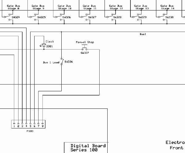
So, to trouble-shoot what is going on, here is a guide. I've included pic's of the schematic and the Digital PCB so that you can locate what I'm referring to. A "High" is a voltage close to the positive rail of your Klee. A "Low" is very close to zero volts.
A. This is the Gate Bus 3 signal. This is the the signal that will be on the row of commoned lugs of the gate bus switches that correspond to gate bus 3. In other words, when you have a Gate Bus Switch set to Gate Bus 3, and the signal on that switch goes high, this signal will go high. For example, if stage 7 is set to Gate Bus 3, and the LED for Stage 7 is lit, the signal at this point should be high.
This signal can be measured at the panel. It connects to Pin 1 of J3, so it should go from the panel to Pin 1 of J3.
To test it, set Stage 7 to on with your pattern bit and hit Load. The Stage 7 LED should go high. Do not clock the Klee - let it stay put. Measure your commoned Gate Bus 3 connections to ensure that Gate Bus 3 is high. Do this for Step B also.
B. This is the same signal as A - it should be present at pin 13 of U12.
C. This is where the Gate Bus 3 signal is NANDed with the clock. If the merge switch is OFF, you should see the Clock signal on pins 10 and 12 of U12. When the Clock LED is on, this signal should be high, when the clock signal is low, this signal should be low. If the Merge switch is on, this signal will be a constant high, regardless of whether the clock is high or low.
To measure this, start clocking the Klee. Turn your Gate Bus 3 Merge Switch off. You should see the signal at this point clocking back and forth from low to high.
D. This is the output of the NAND gate; you should see it on pin 11 of U12 and Pin 3 of U10. If Merge is off, you should only see a low if Gate Bus 3 is high and the clock is high. In other words, say only Stage 7 is set to Gate Bus 3, and the Stage 7 pattern LED is on, and the Clock LED is on, this signal should be LOW (remember, the NAND gate will invert the signal).
If Merge is ON, this signal will go LOW and remain low as long as the Gate Bus 3 signal is high. Again, say only Stage 7 is set for Gate Bus 3, and its LED is on - this signal would be low, and the merge switch being on would allow this signal to remain low as long as the Stage 7 LED is on.
To measure this, set at least one stage (or more) to Gate Bus 3, turn Merge 3 off and watch this point. You should see it transition from low to high and high to low.
E. This is the inverted signal described in D, and may be a bit easier to understand, since you don't have to worry about the inversion. It should be present at pin 4 of U10.
If Merge is off, you should only see a high if Gate Bus 3 is high and the clock is high. In other words, say only Stage 7 is set to Gate Bus 3, and the Stage 7 pattern LED is on, and the Clock LED is on, this signal should be high.
If Merge is ON, this signal will go high and remain high as long as the Gate Bus 3 signal is high. Again, say only Stage 7 is set for Gate Bus 3, and its LED is on - this signal would be high, and the merge switch being on would allow this signal to remain high as long as the Stage 7 LED is on.
To measure this, set at least one stage (or more) to Gate Bus 3, turn Merge 3 off and watch this point. You should see it transition from low to high and high to low.
Let me know what you see, or if this isn't clear, ask me for more explanation. We can continue from there.
| Description: |
|
| Filesize: |
17.6 KB |
| Viewed: |
366 Time(s) |
| This image has been reduced to fit the page. Click on it to enlarge. |

|
| Description: |
|
| Filesize: |
16.97 KB |
| Viewed: |
338 Time(s) |
| This image has been reduced to fit the page. Click on it to enlarge. |

|
_________________
My Site |
|
|
Back to top
|
|
|
tony d
Joined: Aug 31, 2009
Posts: 15
Location: boulder, colorado
|
| Posted: Tue Sep 01, 2009 3:24 pm Post subject:
|
|
|
Hey Scott,
So i hit a brickwall at the very first step. I am getting 0 volts on the common and pin 13.
I checked the switch (good) and the connection between pin 1 of j3 and the common and that was good also.
Don't know if this is useful info or obvious but the led on step 7 goes off when i flip the gate bus position to 3.
Thanks for any help!! i am stumbling in the darkness on this. |
|
|
Back to top
|
|
|
Scott Stites
Janitor
Joined: Dec 23, 2005
Posts: 4127
Location: Mount Hope, KS USA
Audio files: 96
|
| Posted: Tue Sep 01, 2009 4:34 pm Post subject:
|
|
|
It sounds like gate bus 3 may be hooked to ground? Try turning off the Klee and measuring resistance between your gatebus3 signal on the panel and ground - you should have something well above zero Ohms.
_________________
My Site |
|
|
Back to top
|
|
|
Scott Stites
Janitor
Joined: Dec 23, 2005
Posts: 4127
Location: Mount Hope, KS USA
Audio files: 96
|
| Posted: Tue Sep 01, 2009 4:35 pm Post subject:
|
|
|
I keep forgetting to mention that if gatebus 3 is still hooked to the bus 1 load switch, be sure to disconnect that.
_________________
My Site |
|
|
Back to top
|
|
|
Scott Stites
Janitor
Joined: Dec 23, 2005
Posts: 4127
Location: Mount Hope, KS USA
Audio files: 96
|
| Posted: Tue Sep 01, 2009 4:56 pm Post subject:
|
|
|
I'll fix that boo-boo in the build doc. Lucky you for finding it. 
_________________
My Site |
|
|
Back to top
|
|
|
tony d
Joined: Aug 31, 2009
Posts: 15
Location: boulder, colorado
|
| Posted: Tue Sep 01, 2009 5:06 pm Post subject:
|
|
|
| Ok, so on gate bus 3 when checking resistance my meter is freakin'. all over the board but when i test gate bus 1 i get a steady 100k |
|
|
Back to top
|
|
|
tony d
Joined: Aug 31, 2009
Posts: 15
Location: boulder, colorado
|
| Posted: Tue Sep 01, 2009 5:15 pm Post subject:
|
|
|
Thanks Scott, that was the problem. it is know working. audio coming soon !!
Thanks so much man, and i'm serious about the boulder thing it would be the least i could do to show my appreciation! |
|
|
Back to top
|
|
|
Scott Stites
Janitor
Joined: Dec 23, 2005
Posts: 4127
Location: Mount Hope, KS USA
Audio files: 96
|
| Posted: Tue Sep 01, 2009 5:25 pm Post subject:
|
|
|
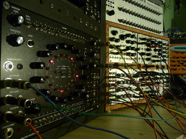
Woo hoo! Post a pic of the Klee, too, when you have the time!
_________________
My Site |
|
|
Back to top
|
|
|
tony d
Joined: Aug 31, 2009
Posts: 15
Location: boulder, colorado
|
|
|
Back to top
|
|
|
Scott Stites
Janitor
Joined: Dec 23, 2005
Posts: 4127
Location: Mount Hope, KS USA
Audio files: 96
|
| Posted: Thu Sep 03, 2009 10:21 am Post subject:
|
|
|
Wow! That Bridechamber panel is sweet. It's very tempting to build another one using that.
Thanks for posting that!
_________________
My Site |
|
|
Back to top
|
|
|
schmidtc
Joined: May 16, 2009
Posts: 34
Location: Boston
|
| Posted: Fri Sep 04, 2009 7:51 am Post subject:
|
|
|
That's a rad set up you're working with Tony. Way to inspire the youth of tomorrow.
Cheers from Boston, Carlos Santini |
|
|
Back to top
|
|
|
tony d
Joined: Aug 31, 2009
Posts: 15
Location: boulder, colorado
|
| Posted: Sat Sep 05, 2009 12:41 pm Post subject:
|
|
|
haha, fancy seein' you here.
glad you like the setup. maybe you will make it back to boulder 1 day and we can do some jammin'
congrats on the engagement also!! |
|
|
Back to top
|
|
|
|

 Forum index » DIY Hardware and Software » Klee sequencer