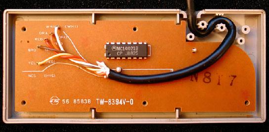
it amazingly documents the CMOS 4021, how nintendo used it in their NES controller and how the author used it in some system of his own design called "hydra".
I will try to post all the results of my research and experiments utilizing this chip, the nes controller as it interfaces into my current lunetta (and i invite all to do the same)
nescont.jpg
Description:
Filesize:
28.03 KB
Viewed:
32519 Time(s)
_________________ home made noise and electronic ill-logic
haha very cool they actually build that entire controller around the 4021. A little while ago someone posted something about the very first pong machines, they were mostly transistors and a few TTL chips(older brother of cmos)
I don't really know much about the 4021 related to music but they are beeing used a lot in microcontroller projects, from the arduino.cc website:
Quote:
Sometimes you'll end up needing more digital input than the 13 pins on your Arduino board can readily handle. Using a parallel to serial shift register allows you collect information from 8 or more switches while only using 3 of the pins on your Arduino.
_________________ There he goes. One of God's own prototypes. A high-powered mutant of some kind never even considered for mass production. Too weird to live, and too rare to die.
Hunter S. Thompson movies noise
Joined: Dec 01, 2005 Posts: 150 Location: Copenhagen - Denmark
Posted: Tue Sep 28, 2010 5:49 am Post subject:
I'll bet that each switch on the controller is connected to a input pin on the shiftrergister, and then the NES mainbox periodically polls the register.
Well it is a great discovery! And just look at the exterior design of the controller too! NICE!! The only problem with posting this sort of information is those #@!? 'circuit benders' will be disrespecting and destroying a load of nice controllers!
heh the only reason i have nes controllers lying around was from my circuit bending days. Im going to a fennesz show tonight, but hopefully tomarrow i'll get a chance to get down an dirty with the 4021 and see if i can figure it out. _________________ home made noise and electronic ill-logic
and after some thought, this is how i plan to attempt to use the nes controller with my lunetta:
According to my research, the NES sends a rather high clock signal to the chip and with each pulse the status of each button is sent back to the nes in a specific order as a data string of high/low/1/0's. (Which i predict will act similar to a 4017 with all the outputs tied via switches.) Whether or not the rate of pulses returned are related to the speed of the clock input (i.e. a division of) is yet to be determined, but i bet it's probable.
I would wire it up like i doodled up in the graphic. The latch output would spit 1 "longer" pulse with each clock pulse in. The Pulse out would send a string of high/lows such as 10110111 or 00110110...but because of how the nes works the data should be flipped with an inverter (if one prefers).
and finally a clock in jack should be wired up too.
I think thats how it would work easiest.
I'll have to think of it a bit more but if it were possible to have 1 out put per button, that would be slick. This i guess would involve how the nes interprets the returned serial data.
nescont1.jpg
Description:
Filesize:
22.92 KB
Viewed:
311 Time(s)
This image has been reduced to fit the page. Click on it to enlarge.
_________________ home made noise and electronic ill-logic
I knew I'd be stirring a wasps nest up mentioning circuit benders! HA HA HA!!!! What's the matter? Didn't you like what Santa made you for Xmas? Look, I can see the joy it gives many.... but it's a bit over-rated if you ask me (not that you DID ask me).RANT ON/ A bit like 'DJ's..... flipping records used to be the mundane job of having a party... along with being the designated bong packer.... not sure how they ended up with 'hero' status! Circuit Benders and DJ's! /RANT OFF
I havent done any physical toying yet (only got one nes controller, dont wanna blow it up) but it turns out the 'latch' jack shown above should be an INPUT not an output.
I guess for the proper function you'd send the latch a slower, divided clock speed and the clock-in a relatively higher speed, for example.
The latch pulse should trigger a 'button check' and return up to 7 data pulses for each button at the incoming clock rate through the pulse/data out jack.
hopefully, more to come... _________________ home made noise and electronic ill-logic
That's a nice looking logic synth you have there! Great colour scheme! I was just wondering though if the D pad on the controller was doing much. Have you noticed a difference in the direction is is pressed or are all directions doing the same thing? Those controllers were a very stylish design, even looking great these days. I think the snes was not as good stylistically.... going off topic here again.....
sweet stuff stolenfat, really creative use of what most people would considder junk .
Seems like the 4021 and the melodygenerator are a perfect match, good to know. Ill add it to my list of things to keep my eyes open for when searching the local thriftstores. _________________ There he goes. One of God's own prototypes. A high-powered mutant of some kind never even considered for mass production. Too weird to live, and too rare to die.
Hunter S. Thompson movies noise
I was just wondering though if the D pad on the controller was doing much. Have you noticed a difference in the direction is is pressed or are all directions doing the same thing?
Well, the d pad does at much as the rest of the buttons, but i'll explain why it seems a little less so:
the bits the 4021 nes controller spits out are in an exact order each time in accordance with the serial input pins of the chips.
A is first B is 2nd... and the d pads are at the end. the A bit for some reason is the strongest, or perhaps the longest, bit and has the most effect, when A and B are pushed together you are basically lengthening the size of the first bit which makes it even stronger (I believe). The d-pads only work one at a time (I THINK) so you cant join them all together to form 1 long giant bit, you end up getting 3 lows and 1 high (if you use an inverter) equaling one small quick bit- which is why it may seem like it isnt doing much to the enable pin of the slacker melgen. To a 4040 divider the d-pad bits have as much effect as the A button bit.
Quote:
nes-data.gif
Description:
as you can see in this image, the A button bit is way bigger than the rest- prolly to correspond with the latch input. the nes can read this just fine, but it affects the lunetta differently.
Filesize:
3.47 KB
Viewed:
329 Time(s)
This image has been reduced to fit the page. Click on it to enlarge.
_________________ home made noise and electronic ill-logic
the latch input is actually just a pin on the controller connector. I havent done any soldering to the 4021, just the connector.
nintendo has it wired up in such a way that it needs a 'latch' pulse, i cant confirm nintendo's controller schematic since i havent busted mine open to take a peak. A regular 4021 seems a bit more complicated and has 3 outputs, and may not need a latch pulse.
its all very well documented in the links above, or google "4021 NES"
helpful? its still a mystery to me kinda _________________ home made noise and electronic ill-logic
yea dr. offset- i predict that any amount of buttons could be used to set the parallel inputs of the 4021 to either V+ or Ground to get some sort of effect. More research needs to be done, but im at a pause till i get some 4034s
edit: im glad my vids are inspiring you because your vids totally inspired me wowowoweee _________________ home made noise and electronic ill-logic
Eight NES controller buttons, 8 parallel inputs at the 4021.
Here are sections of the 4021 datasheet , and setup with 8 "set parallel in" switches and "manual load". I made the JPG when I was into making little modules on small circuitboards I got from Inventor.
Not shown: If you want your pattern to recirculate once loaded you need to connect pin 3 (Q8 out) to pin 11 (serial in).
I drew this as a hardwired module just to get my head around the workings of the chip.
Lately I've developed a fondness of the dual 4-bit 4015 shiftregister. Since building on circuitboard (so no panels with switches) I abandoned using the 4021. But hey, the "load parallel" feature with recirculating the bits was nice indeed. Thanks for the reminder.
Stolenfat this is great. I've been lurking around, and I'm preparing to build some lunetta stuff. Incorporating a NES controller is just ridiculously cool.
I can inform you that I have checked one of my own NES controllers to this schematic. All was the same EXCEPT R1 and R2 is NOT there. Maybe they are internal in the NES console itself.
Also I can inform you that a SNES controller contains 2 x 4021, and has 12 individual buttons.
Welcome to the forum, and especially the lunetta subsection.
Quote:
Also I can inform you that a SNES controller contains 2 x 4021, and has 12 individual buttons.
ah, thanks for that! Now I am wondering what other nintendo or sega products contain the 4021, raygun anyone? _________________ There he goes. One of God's own prototypes. A high-powered mutant of some kind never even considered for mass production. Too weird to live, and too rare to die.
Hunter S. Thompson movies noise
the zapper actually uses the different ports on the controller connector that the usual nes controller doesnt use. _________________ home made noise and electronic ill-logic
You cannot post new topics in this forum You cannot reply to topics in this forum You cannot edit your posts in this forum You cannot delete your posts in this forum You cannot vote in polls in this forum You cannot attach files in this forum You can download files in this forum

 Forum index » DIY Hardware and Software » Lunettas - circuits inspired by Stanley Lunetta