| Author |
Message |
Uncle Krunkus
Moderator

Joined: Jul 11, 2005
Posts: 4761
Location: Sydney, Australia
Audio files: 52
G2 patch files: 1
|
 Posted: Thu Jan 04, 2007 4:59 am Post subject: Posted: Thu Jan 04, 2007 4:59 am Post subject:
|
  |
|
No, there's no problem with the 10M resistor. I built it when I first did the layout, and the filter pot worked fine. Check all the cuts in the stripboard. This is very easy to get stuck on if you haven't done much stripboarding before. Let me know how you go.
_________________
What makes a space ours, is what we put there, and what we do there. |
|
|
Back to top
|
|
 |
LukeDI

Joined: Sep 23, 2006
Posts: 50
Location: Boston MA, USA
|
| Posted: Thu Jan 04, 2007 2:06 pm Post subject:
|
|
|
| Quote: | | Check all the cuts in the stripboard. |
I probably did screw those up.  I munged it up a few times before I did it right. (or mostly right as the case may be) Unfortunately my 'work bench' has been superseded by Christmas detritus for the moment so I can't check it right now. I munged it up a few times before I did it right. (or mostly right as the case may be) Unfortunately my 'work bench' has been superseded by Christmas detritus for the moment so I can't check it right now. |
|
|
Back to top
|
|
|
Chrometuna
Joined: Aug 14, 2006
Posts: 209
Location: Topeka
Audio files: 3
|
| Posted: Mon Jan 15, 2007 6:39 am Post subject:
|
|
|
| Uncle Krunkus wrote: | Here's an x-ray copperside cutting guide. Yellow=cut. Grey=solder point.
Oh, and a rough parts list. My designators aren't exactly the same as the original schem so check this. I'll fix that later.
See ya |
It shouldnt be a surprize to anyone now, that I am a real "DIFM" (Do It For Me) kinda guy, rather then a DIY guy.
I tried making a PCB from Lorenzo's Weird Sound Generator layout.
The MAJOR problem with it is that it just wont fit on the copper clad blanks you get from Radio Shack (I have no other real source for stuff here) SDo I tried modifying it a bit. But the fact that the pots etc are "On Board" is drawback.
So what I need someone to DIFM (Do It For Me) is to design a pcb layout that will fit on a 4X6" board that has the pots and jacks and switches OFF of the board, so I can put them in my own case design (Along side my soundlab)
OR:
An idea that hit me (ouch) was that perhaps I could etch Uncle's strip board layout onto a PCB, and that might even be EASIER to buuild up.
SO, what Im asking for someone to DIFM is a layout of basicaly Uncle's (Uncle, could YOU do this? Please? I'm sure other noobs would benifit, as many of us cant get strip board) stripboard layout that could be burned onto a PCB?
I could probably figure it out all by myself, but that would go against my DIFM spirit. (That and my brain is in the shop still, it was only firing on the reptilian brain stem, and little else was working) It would probably on take loading the image into photoshop, or gimp, or whatever one uses, and playing with contrast and such to make the layout, but me not truely and really understanding the circuit (How did I EVER get a soundlab built and working the first try????) would probably tuna it up.
Anyhelp? Please?
Cheers
bob cutler |
|
|
Back to top
|
|
|
Chrometuna
Joined: Aug 14, 2006
Posts: 209
Location: Topeka
Audio files: 3
|
| Posted: Mon Jan 15, 2007 9:20 am Post subject:
|
|
|
deleted, see my other post
Last edited by Chrometuna on Thu Jan 18, 2007 10:44 pm; edited 1 time in total |
|
|
Back to top
|
|
|
Uncle Krunkus
Moderator
Joined: Jul 11, 2005
Posts: 4761
Location: Sydney, Australia
Audio files: 52
G2 patch files: 1
|
| Posted: Tue Jan 16, 2007 2:09 am Post subject:
|
|
|
Looks fine to me. You just have to make sure you transfer it to the PCB the right way around. (I can't do that for you!  ) )
You can get stripboard, and you can get PCB blanks of the right size. Just order them online.
You'll become more of a DIY kind of person, as soon as people stop doing things for you!  I don't say that to be nasty or unkind, I just know that it's true. The stuff which I know and take for granted now, I've learned by doing a lot of stuff, getting things wrong, and getting motivated to re-do them. I don't say that to be nasty or unkind, I just know that it's true. The stuff which I know and take for granted now, I've learned by doing a lot of stuff, getting things wrong, and getting motivated to re-do them.
Technical proficiency is 10% theoretical knowledge and 90% bravery!  (immunity to the fear of fucking something up! (immunity to the fear of fucking something up!  ) It does take practice and patience, but it's not beyond learning, as long as you're interested in the details. ) It does take practice and patience, but it's not beyond learning, as long as you're interested in the details.
_________________
What makes a space ours, is what we put there, and what we do there. |
|
|
Back to top
|
|
|
fluxmonkey
Joined: Jun 24, 2005
Posts: 708
Location: cleve
|
| Posted: Tue Jan 16, 2007 9:17 am Post subject:
|
|
|
| Chrometuna wrote: | | The MAJOR problem with it is that it just wont fit on the copper clad blanks you get from Radio Shack (I have no other real source for stuff here) SDo I tried modifying it a bit. But the fact that the pots etc are "On Board" is drawback. |
bob--
you can order blank PCB material online at gajillions of places... i use Mouser or Jameco, tho there are cheaper places (www.jameco.com, part #616500 for 6x9", for instance). suck it up, you'll have to get used to ordering parts online, ratshack just won't cut it.
and just because the layout allows pots to be mounted on the board doesn't mean you have to... just solder wires where between the pots and the board, you're good to go.
lbd |
|
|
Back to top
|
|
|
Chrometuna
Joined: Aug 14, 2006
Posts: 209
Location: Topeka
Audio files: 3
|
| Posted: Tue Jan 16, 2007 1:15 pm Post subject:
|
|
|
I deleted the layouts of my PCB layout version of Andrew's stripboard layout.
I wouldnt want anyone to try to use those: They where out of proportion and the IC's wouldnt fit it.
I DID re-work them and got a version that WOULD work.....But last night a bungled an etching process so badly I now think that layout is cursed (Not the Stripboard version, but my PCB version)
But someone else could, and should try their hand at it sometime.
Cheers!
bob c
Last edited by Chrometuna on Thu Jan 18, 2007 10:43 pm; edited 1 time in total |
|
|
Back to top
|
|
|
Chrometuna
Joined: Aug 14, 2006
Posts: 209
Location: Topeka
Audio files: 3
|
| Posted: Tue Jan 16, 2007 1:31 pm Post subject:
|
|
|
| Uncle Krunkus wrote: | Looks fine to me. You just have to make sure you transfer it to the PCB the right way around. (I can't do that for you! )
You can get stripboard, and you can get PCB blanks of the right size. Just order them online.
You'll become more of a DIY kind of person, as soon as people stop doing things for you! I don't say that to be nasty or unkind, I just know that it's true. The stuff which I know and take for granted now, I've learned by doing a lot of stuff, getting things wrong, and getting motivated to re-do them.
Technical proficiency is 10% theoretical knowledge and 90% bravery! (immunity to the fear of fucking something up! ) It does take practice and patience, but it's not beyond learning, as long as you're interested in the details. |
Yup. I know what you're saying. I *USED* to know a lot of electronic stuff, but I lapsed on using my brain....on top of frying half of it....careful on voltages too high in DIY shock therapy!
About 10 years ago, I built my OWN pirate radio station. Thats part of my DIY philosopheee. If you dont like what top-40 radio is playing, then make your OWN station! I built the first one from a Ramsey kit (Yuck) and then put a linear power amp to it. The next one I built from scratch (Using instructions and diagrams from somewhere else...I STILL didnt truly understand the circuits and what they where doing, BUT I started getting a good idea about what was going on in the wiring and parts.
And, as a reward and affirmation that my stuff worked....I got a visit from the FCC, who luckily didnt confiscate my stuff, but they left a nasty warning for me after grilling me. They said I was 3000 times over the legal limit. I waited two weeks, and fired it up again. But I only broadcasted a couple of hours a night, not 24/7 like I HAD been.
Things are coming back slowly for me now that I am getting back into electronics. Most of the questions I ask are really trying to confirm or make sure of things I am unsure about....OR that I cant find through a search of this forum. (And this forum is a GREAT library of info, and 90% of the things I need to know I can find through a search and reading. Because someone somewhere has already had most of the problems I currently was dealing with. And someone has helped them.
But sometimes I just cant find the answers I seek....and feel like if *I* cant find them, then someone ELSE probably couldnt find them, so a new searchable thread might be needed here, even if it sounds stupid.
If I had even ONE extra IQ point, I probably wouldnt need to ask ANY questions, and could just figure things out for myself. But Ive also got a couple of problems with my brain...and when I'm trying to figure out a difficult problem (Like shoetieing or spelling) my brain suddenly switches channels and I have Bugs Bunny and Daffy chasing each other through my head....OR, I have this: http://www.youtube.com/watch?v=KC9FtLQJoGM
Anyway, I really DO appreciate all the help! |
|
|
Back to top
|
|
|
Chrometuna
Joined: Aug 14, 2006
Posts: 209
Location: Topeka
Audio files: 3
|
| Posted: Tue Jan 16, 2007 8:27 pm Post subject:
|
|
|
For anyone contemplating using the layout I posted above (From Andrew's stripboard layout)
DONT USE IT!
It is not to scale, and I just spent an hour or so at Kinkos figuring that out. No amount of resizing, enlarging, shrinking or anything would put it to the right size for the pins in the IC chips to fit onto the board properly. (Thank God that I didnt try burning the board without checking this out first)
So I need to take it back into photoshop and re-proportion it.
The thing I liked about the idea of using Andrews strip board layout as a circuit board layout was that it didnt really have to be sized too closely as far as drilling the holes (LOTS of room to play with there) BUT, the ICs *HAVE* to be right on the money.
Once I get something usable, I'll post that, and then delete the other posts so no one is tempted to think that they can burn a board directly from that.
Cheers
blabbing bob....who is ranting a lot on the internet toay. |
|
|
Back to top
|
|
|
Uncle Krunkus
Moderator
Joined: Jul 11, 2005
Posts: 4761
Location: Sydney, Australia
Audio files: 52
G2 patch files: 1
|
| Posted: Wed Jan 17, 2007 3:01 am Post subject:
|
|
|

_________________
What makes a space ours, is what we put there, and what we do there. |
|
|
Back to top
|
|
|
Chrometuna
Joined: Aug 14, 2006
Posts: 209
Location: Topeka
Audio files: 3
|
| Posted: Thu Jan 18, 2007 10:53 pm Post subject:
|
|
|
OK
I did a re-working of Lorenzo's WSG PCB layout.
It now fits on a 4X6 inch copper clad PCB blank, like what is available at Radio shack.
Some components are now "Off board" and others just moved a little bit. It should be too hard to figure out what I moved around, just compare it to Lorenzo's board.
I did a "Normal" version, and then a "Fat line" version that might help klutzes like me in the photopaper etching process.
I ALSO discovered a product that works really well for removing the toner before or after etching:
Its called "Get Off!" Ink and Adhesive remover.
Its in a spray can, and probably available at office suply places. Its used for cleaning up printers, fax machines, ink etc. The guy behind the counter at Kinkos "Loaned" me a half empty (Or full?) can of it, and it works really well.
Heres the layouts:
| Description: |
|
| Filesize: |
65.59 KB |
| Viewed: |
26249 Time(s) |

|
| Description: |
| This is the "Normal" version. The other one is the "Fat Line" version. I havnt tried etching or building these yet. |
|
| Filesize: |
429.24 KB |
| Viewed: |
21545 Time(s) |

|
|
|
|
Back to top
|
|
|
dobart

Joined: Feb 20, 2007
Posts: 10
Location: SEATTLE
|
| Posted: Tue Feb 20, 2007 12:16 pm Post subject:
WSG theory of operation |
|
|
Hi folks! Been here a bunch of times as I browsed circuit sources and whatnot. Nice to be here.
Anyway, I have a few WSGs and am impressed with the sound: much less square than raw oscillators, even without the filter!
Which leads me to: I want to use the signal from the WSG circuit (pre-filter) to drive some other oscillators, a divider IC and pulse LEDs for vactrolling... BUT the output signal of the WSG won't even kick over an inverter!
Is this due to the transistor modulation? I can gang the 3 oscillators on the 40106 and be just fine, but setting up as a WSG means I can't use the waveform to drive and tweek other doodads... dividers, NAND gates, etc.
Any ideas?
Oh: knobs: small bear electronics, and mouser- if you order from mouser you get the catalog, which is epic. Oh: perfs and stripboards: FUTURLEC: lots of different kinds, great pricing, easy search. Just give em a few weeks to deliver form Thailand.... |
|
|
Back to top
|
|
|
sputnik
Joined: Feb 23, 2007
Posts: 2
Location: Montreal
|
| Posted: Fri Feb 23, 2007 3:37 pm Post subject:
|
|
|
Hi everyone! This is my first post to this site!
I have constructed the WSG stripboard, but I am having trouble getting the filter portion of the circuit to work. Both "zany-wacky-wierd" circuits seem to be fully functional (that is, the signal from each circuit to ground produces what seem to be the proper bleeps, and all 4 knobs and the switch on both sides affect the sound as they should). Therefore, I think the problem must be in the filter portion. On connecting the line out from the filter to an amplifier, the following noises are heard: 1/2 second of the proper output, a pop, 1 second of very faint output with buzzing, another pop, 2 seconds of silence, and then back into the 1/2 second of normal bleeps. I have checked the circuit fairly thoroughly, replaced most of the capacitors, replaced the LM741...I don't know what else to check. What would make a circuit cycle like that? Unfortunately, I don't have a digital camera, but I can record the sound the circuit is making if that would help. Thanks in advance! I'm really stumped on this one. I'm kind of a beginner when it comes to circuits, but I'm fairly proficient at soldering, and i'm pretty confident there aren't any solder bridges or anything. But I could be wrong! Let me know what you think.
-Serge |
|
|
Back to top
|
|
|
Uncle Krunkus
Moderator
Joined: Jul 11, 2005
Posts: 4761
Location: Sydney, Australia
Audio files: 52
G2 patch files: 1
|
| Posted: Sat Feb 24, 2007 12:36 am Post subject:
|
|
|
I remember Ray saying something about the cap which backs up the pseudo split supply, when someone had a similar problem. Make sure that cap is the right way around. By pseudo split supply, I mean the arrangement for the 741 which is the heart of the filter. I just had a look, and it's C7.
The symptoms you describe sound like what happens when an electrolytic is reverse biased. The dielectric breaks down and behaves "differently", and can sometimes be re-polarized, in which case it sounds better for a few seconds, but then ultimately fails and goes weird again etc. You're lucky it hasn't actually gone "pop"
_________________
What makes a space ours, is what we put there, and what we do there. |
|
|
Back to top
|
|
|
dobart
Joined: Feb 20, 2007
Posts: 10
Location: SEATTLE
|
| Posted: Sun Feb 25, 2007 1:31 pm Post subject:
|
|
|
| Uncle Krunkus wrote: | I remember Ray saying something about the cap which backs up the pseudo split supply, when someone had a similar problem. Make sure that cap is the right way around. By pseudo split supply, I mean the arrangement for the 741 which is the heart of the filter. I just had a look, and it's C7.
The symptoms you describe sound like what happens when an electrolytic is reverse biased. The dielectric breaks down and behaves "differently", and can sometimes be re-polarized, in which case it sounds better for a few seconds, but then ultimately fails and goes weird again etc. You're lucky it hasn't actually gone "pop" |
yup, not in front of the schematic but, the split supply is the 2 1mohm resistors with the cap in the middle... (with electrolytic DEFINITELY pointing the right way- one of the 1st things I check as I have enough popcorn) THAT'S an interesting filter, btw... I want to set one up and play with the cap values (470pf-ish) between the 10mohm resistor; kind of figure it out... I'm thinking it's one of those wien bridge or twin T kind of things, but I haven't sat down and fiddled with it enough yet to be too sure... it sounds great.
The issue I was having was from the output of the oscillator stage, BEFORE the filter; essentially where the first jack is: for some reason this output will not trigger a gate or an inverter: I want to send it into a 4040 counter to send flashes to feedback LEDs and whatnot.
What I didn't think to do was check each output leg of the oscillator IC: maybe I could get a logic signal out of the existing circuit through a 10k resistor to pin 2, for example... or pin 4 or 6. As long as it roughly represented the overall output signal that'd be enough: then into a divider and off to flash LEDs
What I wound up doing was reassembling the oscillator into 2 summed 3-way oscillators and got perfectly usable logic from the same IC. (For a 'lightsynth table' kind of thing: box on legs with dangling octupus arms used to control it in various ways). On the same breadboard, with or without the filter stage active, it works fine.
here it is, sprouting jumpers to check the signal; pre-WSG rewiring (perfboard daughtercard!)
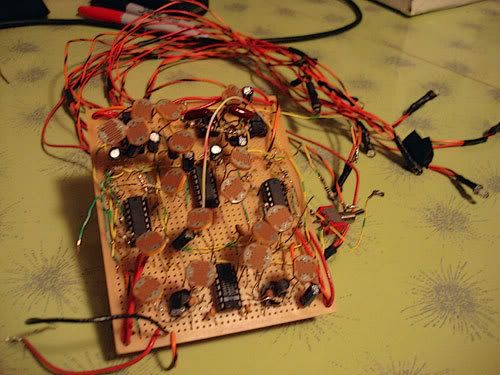
Maybe the transistor is doing something to the output waveform the way it mixes in that long wavelength? I have to get a scope on it at some point, but I'm off on a work trip for the week.
If I can figure it out for my next stripbpard core (to mount in a handheld geiger counter, with all the controls and LDRs: mount the LEDs into goggles connected to the handheld unit via cable!) I'd like to use it. |
|
|
Back to top
|
|
|
dobart
Joined: Feb 20, 2007
Posts: 10
Location: SEATTLE
|
| Posted: Sun Feb 25, 2007 1:32 pm Post subject:
|
|
|
| sputnik wrote: | Hi everyone! This is my first post to this site!
I have constructed the WSG stripboard, but I am having trouble getting the filter portion of the circuit to work. Both "zany-wacky-wierd" circuits seem to be fully functional (that is, the signal from each circuit to ground produces what seem to be the proper bleeps, and all 4 knobs and the switch on both sides affect the sound as they should). Therefore, I think the problem must be in the filter portion. On connecting the line out from the filter to an amplifier, the following noises are heard: 1/2 second of the proper output, a pop, 1 second of very faint output with buzzing, another pop, 2 seconds of silence, and then back into the 1/2 second of normal bleeps. I have checked the circuit fairly thoroughly, replaced most of the capacitors, replaced the LM741...I don't know what else to check. What would make a circuit cycle like that? Unfortunately, I don't have a digital camera, but I can record the sound the circuit is making if that would help. Thanks in advance! I'm really stumped on this one. I'm kind of a beginner when it comes to circuits, but I'm fairly proficient at soldering, and i'm pretty confident there aren't any solder bridges or anything. But I could be wrong! Let me know what you think.
-Serge |
Sorry, missed your post! |
|
|
Back to top
|
|
|
sputnik
Joined: Feb 23, 2007
Posts: 2
Location: Montreal
|
| Posted: Tue Feb 27, 2007 5:44 pm Post subject:
|
|
|
| I found my problem...it was just a simple mistake. I had one of the C7 pins soldered into the wrong strip. After corrercting that, the WSG is making great sounds. The filter really is key to its awesomeness. Thanks for the design! |
|
|
Back to top
|
|
|
Wild Zebra

Joined: Apr 28, 2005
Posts: 806
Location: Ohio
Audio files: 5
|
| Posted: Fri Mar 02, 2007 11:44 am Post subject:
Adding a filter in ? |
|
|
Hello there. Over a EA forums a chap added a filter in to his WSG. Between R7 and C1 via the 1m resistor. Marked "from second circuit if needed". Well I ran my APC through and it was barely audible. Of course with no resistor it was fine. But, will I damage the circuit? Could I just throw a 100k in thar? Or a pot to control the amount? I was going to just put a 100k in there, but figured I'd ask for some opinions.
_________________
"your stripes are killer bro" |
|
|
Back to top
|
|
|
Randaleem
Joined: May 17, 2007
Posts: 456
Location: Northern CA, USA
|
| Posted: Fri Jun 01, 2007 4:49 am Post subject:
|
|
|
Hi,
You'd probably want to start with one of the existing schematic capture programs. Work your algorithm to their existing parts and schematic interconnect database(Netlist). OrCAD would be one choice for format; as it is an industry standard. But expensive.
Circad by Holophase has a small and elegant database and part description. Eagle is perhaps more widely known and its ULP's (User Language Programs; A powerful API) would let you do all that is needed I'd guess. Both Eagle and Circad already have autorouters in addition to their API's. FWIW, an "alley" type autorouter would be tailor-made for running stripboard designs. (this algorithm seeks to run everything in rows/alleys; horizontal on one side and vert on the other! Only after that's exhausted does it go for non-alley routes.
Agreed that the modular approach is cool; often there already is existing prior useful work.
Hope this helps,
Randal
| Macaba wrote: | Obviously, i'd stick to all the components that ADHDboy ever uses in his stuff, like the common op-amps and capacitors. And extra components would become available on demand. The key is making the program modular, so I can easily add components.
Ever since i've started to build my analogue modular synth, I've been a real big fan of modular design!  |
|
|
|
Back to top
|
|
|
Phallus Dei
Joined: Jan 21, 2007
Posts: 18
Location: Scotland, UK
|
| Posted: Mon Jul 02, 2007 10:27 am Post subject:
|
|
|
Ok I'm building this monster! I've got all the parts on order. Got a few questions.
Firstly, is Stripboard ok to cut? Say I build the circuit on an oversized board, can I hack it up?
Secondly, is there a volume control. As much as I love the eccentric terms for the controls, is one of the "Wacky" pots just a plainjane volume? Or will I be so engrossed with the encyclopedia of sounds that volume swells wont be needed?
Thirdly, do those ICs solder straight on the board, or should I get chairs for them? I can get 14 pin and 8 pin chairs no bother, and I'm not a perfect solderer, so will the chairs be a safer option (less risk of frying).
In return I promise to send in photos of the completed thing, once I get a case for it (I'm raiding the local thrift stores!). |
|
|
Back to top
|
|
|
Wild Zebra
Joined: Apr 28, 2005
Posts: 806
Location: Ohio
Audio files: 5
|
| Posted: Mon Jul 02, 2007 12:35 pm Post subject:
|
|
|
| Quote: | | Firstly, is Stripboard ok to cut? Say I build the circuit on an oversized board, can I hack it up? |
Sure just score it and snap, but there is a stripboard layout provided. I'd recommend sizing it first, just so you don't accidently mess your completed circuit.
| Quote: | | Secondly, is there a volume control |
no, you'll have to add that
| Quote: | | Thirdly, do those ICs solder straight on the board |
I'd say it's good practice to use sockets. It saves alot of hassle if you fry a chip.
Have fun hope that helps
_________________
"your stripes are killer bro" |
|
|
Back to top
|
|
|
Phallus Dei
Joined: Jan 21, 2007
Posts: 18
Location: Scotland, UK
|
| Posted: Tue Jul 03, 2007 6:46 am Post subject:
|
|
|
| Thanks! I'm planning to build this in a first aid box, to give me a baby VC3 thing! |
|
|
Back to top
|
|
|
Phallus Dei
Joined: Jan 21, 2007
Posts: 18
Location: Scotland, UK
|
| Posted: Thu Jul 05, 2007 7:33 am Post subject:
|
|
|
ok Thanks!
Capacitor problems (I got replacements for the WIMA oranges)!!!
Does the 220uF caps have to be non-polar? Do the other non-polar capacitors have to be this way? I saw the photos of the stripboard earlier, and some of those caps appear to be the usual disk ones. |
|
|
Back to top
|
|
|
Phallus Dei
Joined: Jan 21, 2007
Posts: 18
Location: Scotland, UK
|
| Posted: Fri Jul 06, 2007 12:22 pm Post subject:
|
|
|
| Is a 2.2uf Capacitor same as a 220? |
|
|
Back to top
|
|
|
Uncle Krunkus
Moderator
Joined: Jul 11, 2005
Posts: 4761
Location: Sydney, Australia
Audio files: 52
G2 patch files: 1
|
| Posted: Sat Jul 07, 2007 1:04 am Post subject:
|
|
|
No,
A 2.2uF will be bigger, and most likely polarised.
220 means 220pF which is 1/10000th the value, smaller, possibly a ceramic disc, and not polarised.
_________________
What makes a space ours, is what we put there, and what we do there. |
|
|
Back to top
|
|
|
|

 Forum index » DIY Hardware and Software » MusicFromOuterSpace.com designs by Ray Wilson
