| Author |
Message |
Dozius
Joined: Feb 26, 2009
Posts: 6
Location: Canada
|
|
|
Back to top
|
|
 |
Tony Deff
Joined: May 25, 2008
Posts: 51
Location: Suffolk, UK
|
 Posted: Tue Mar 10, 2009 7:59 am Post subject: Posted: Tue Mar 10, 2009 7:59 am Post subject:
|
  |
|
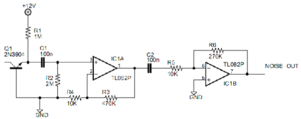
It's been decades since I've seen a reverse-biassed 2N3904 in Practical Electronics! (giving my antiquity away). I cannot remember whether the impedance of such an arrangement is low (as a zener) or somewhat higher.
Does the noise cut-out for a couple of seconds, or until switch-off?
The first could be the long time-constant of the high-value resistors, the second could indicate a latch-up in the IC.
Try measuring the d.c voltage at pins 1 & 7 both under normal conditions and if the noise disappears. If pin 1 is near the rail, you could have some leakage bias, amplified by 47.
One obvious source of problems is a direct source from a spike in the +12V into op-amp pin 3. Try splitting the 1M into two 470K, with a decoupling cap at the junction.
Look for similar direct path in your VCO.
PS A high gain in the first stage is a technique used to NOT worsen the noise figure! Try swapping the two gains around. It may not make much difference for a low-noise amp and low-noise resistors, but it would help any dc bias problem.
Bonne chance, |
|
|
Back to top
|
|
|
Dozius
Joined: Feb 26, 2009
Posts: 6
Location: Canada
|
| Posted: Tue Mar 10, 2009 12:07 pm Post subject:
|
|
|
I didn't have any Zeners laying around but I had plenty of 2N's, so I just went with that in my design. 
I did manage to work out exactly what was going on. I strapped decoupling caps close to the power source of the active ICs in each section and things started to behave normally again. I think the problem was a spike cause by the 555 switching. I've also separated the noise section power from the rest of the circuit using 10 ohm resistors and some caps to prevent noise getting in the power lines. So far, this seems to have been enough.
I'll look into splitting direct lines as you suggested and switching around the gain stages for maximum noise.
Thanks for the tips! Much appreciated. |
|
|
Back to top
|
|
|
frijitz
Joined: May 04, 2007
Posts: 1734
Location: NM USA
Audio files: 54
|
| Posted: Wed Mar 11, 2009 3:57 pm Post subject:
Re: Buffering and Decoupling |
|
|
| Dozius wrote: | | Hello, I'm fairly new to the world of building analog synths. I'm studying electronics in school, so it's been a lot of fun applying my learning to this realm. I'm probably going to have a lot of stupid questions, please bear with me. |
Welcome! There are a lot of practical things you need to know that they don't teach in school, and this is one of the best places to learn about them. Your questions so far are good ones. (Not that there are any bad ones!)
| Quote: | | For my first little project I'm putting together a little table-top synth with a couple oscillators, envelopes, SVF and a noise source. I seem to be having issues with decoupling between sections. I've attempted to put decoupling caps close to where the supply connects to each section but I still get pitch changes when my envelope is triggered and my noise source likes to completely cut out sometimes when something is switched in a different section. |
Most decoupling problems have to do with routing of PS lines and PS regulation. You should run the PS leads from each module directly back to the PS itself. This is called "star" distibrution. Use heavy leads (e.g. 18 ga). What are you using for a PS?
| Quote: | | I've used op-amp buffers in the signal path to isolate the various sections, except on my noise source where I'm using a gain stage but no buffer because it would increase my chip count and I thought an op-amp even as a gain stage still gives the high in Z and low out Z characteristic. Do I really need a op-amp buffer there? |
No, you do not. If you are driving a long load you may have some problems from its capacitance. You might want a small cap across R6.

Ian |
|
|
Back to top
|
|
|
Dozius
Joined: Feb 26, 2009
Posts: 6
Location: Canada
|
| Posted: Wed Mar 11, 2009 4:49 pm Post subject:
Re: Buffering and Decoupling |
|
|
| frijitz wrote: |
Most decoupling problems have to do with routing of PS lines and PS regulation. You should run the PS leads from each module directly back to the PS itself. This is called "star" distibrution. Use heavy leads (e.g. 18 ga). What are you using for a PS? |
Right now I'm just using a little bench PS that I built a long time ago. Only put's about 500mA before it starts to choke but it's been good for testing so far. I plan on using a beefier design with very large regulating caps in the final design.
| frijitz wrote: |
No, you do not. If you are driving a long load you may have some problems from its capacitance. You might want a small cap across R6. |
So that's what those are for. See I've always seen those small 47pF caps in the feedback paths and wondered what they were for. I was under the impression they were to keep DC from building up in feedback paths.
I don't think it will be a problem in this case however since everything will be on the same board and traces as tight as I can manage.
Thanks for clearing up some mysteries for me!
-d |
|
|
Back to top
|
|
|
Tony Deff
Joined: May 25, 2008
Posts: 51
Location: Suffolk, UK
|
Posted: Tue Mar 17, 2009 2:19 pm Post subject:
Power Distribution
Subject description: and what is, and is not, revealed to this forum |
|
|
I would agree with frijitz , but would emphasise that Earth returns are extremely important, especially when audio amplifiers are included.
What is high-lighted in these pages, in the way of partial circuits, can be extremely misleading, as when a mystery-novel writer omits to tell the reader certain essential clues until the last page.
By spot-lighting one particular circuit, our attention is distracted from the wider scene. If you had mentioned the use of a 555, for example, a dozen readers would have leaped upon you to mention decoupling.
You do not mention what audio amplification you have included — a headphone buffer is one thing, but if you have a speaker output, involving significant currents, then star-point earthing is essential to prevent significant earth-loop currents inducing a differential voltage in various circuits along the way.
I still remember an electronics designer from work saying how he'll never make the mistake of mixing digital electronics with power amplifiers on the same board again.
Makes me realise what a hopeless task doctors have in diagnosing illness from what we choose to tell them! |
|
|
Back to top
|
|
|
Dozius
Joined: Feb 26, 2009
Posts: 6
Location: Canada
|
| Posted: Wed Mar 18, 2009 11:27 am Post subject:
|
|
|
| I realize I left a lot out. The circuit is enourmous and I just needed some general type advice on decoupling. All the pointers I got were great and I think I can avoid these problems in the future now. |
|
|
Back to top
|
|
|
|

 Forum index » DIY Hardware and Software » Developers' Corner