| Author |
Message |
Captain Biscuits
Joined: Jun 11, 2010
Posts: 116
Location: Northampton, UK
|
 Posted: Mon Aug 30, 2010 3:43 pm Post subject:
Help with understanding Audio/CV and AC/DC Posted: Mon Aug 30, 2010 3:43 pm Post subject:
Help with understanding Audio/CV and AC/DC |
  |
|
Hi
Having built a WSG, Mini Synth, 10 step and Wall Wart power supply I’m setting out to build a modular synth based, to start with at least, on MFOS modules.
I’m making up blocks of 3 modules on A4 metal boards which lets me do the panel printing and laminating cheaply and easily. I’ve just completed my first block - three MFOS VCOs.
Having completed them I’m faced with a problem which I guess will still be around even when I’ve added many more modules - the desire to attenuate outputs, mix outputs and route multiple outputs into one.
I’m learning as I go so I’ve got a few rather naïve questions if anyone has the time to clarify a few points and offer some advice.
For now, to be able to hear all three oscillators at once and to get the level down to something that isn’t too loud through my amp I’ve just wired four 1/4” jack sockets together and am inputting into 3 of them and using the fourth to output. Then I’m just attenuating the output as Ray suggests here http://www.musicfromouterspace.com/analogsynth/oddsandends.html#POTDIVIDER
Advice wise I’d be interested to know what people think would be a useful set of functions for a multiple module given that I’m planning for it to take up a full A4 size block of space and would like it to be adaptable so I can experiment with patches as I add modules. At the moment I’m thinking of a passive 4 input mixer, 3 or 4 simple attenuators (each just In, Pot and Out) 2 or 3 groups of 4 sockets wired as I’ve described above, Ray’s active mixer (with the headphone amp) and the MFOS CV distributor.
So does that make any sense to those of you who have a lot more experience of modulars than I do? Any advice of what I might add in or miss out would be very welcome.
Now for the naïve questions! On Ray’s pot divider page he makes a distinction between AC Signal and DC Input which has thrown me a bit. I’ve been a bit puzzled about the degree of overlap between Control Voltages and Audio Signals which seem to be interchangeable much of the time but not all of the time. On the MFOS pages there is an Ultra Simple Mono Mixer and a Dual 4 Input DC Mixer. They are clearly rather different and I’m struggling to understand why.
Can anyone explain to a simple but not stupid person what is going on here, how I can make a functional multiple module and where I could go horribly wrong if I start slinging all of my outputs and inputs in together?
Many thanks in advance to anyone who can help throw some light on all of this!
All the best,
Ian |
|
|
Back to top
|
|
 |
prinsen
Joined: Jul 21, 2008
Posts: 5
Location: Copenhagen
|
| Posted: Wed Sep 01, 2010 5:20 pm Post subject:
Re: Help with understanding Audio/CV and AC/DC |
|
|
Can't offer you much advise, sorry. But just wanted to comment this:
| Ian Wilson wrote: | | On the MFOS pages there is an Ultra Simple Mono Mixer and a Dual 4 Input DC Mixer. They are clearly rather different and I’m struggling to understand why. |
No, actually they are almost identical. The main difference being the AC coupling capacitors on the inputs of the AC-(or audio-, if you will) mixer. The capacitors block any DC from going to the summing part of the AC-mixer.
Basically the first opamp of both mixers sums the inputs.
For the DC mixer the max. amplification is 100k/100k or 1, so the mixer will either attenuate the input control voltage, if you increase the resistance of the first of the 100k resistors (using the 100k pot), or pass it unattenuated.
For the AC mixer the max. amplification is a little more complicated to calculate, due to the 39k resistor and the 22p capacitor acting as a low pass filter, but should be about 2 at audio frequencies. More or less 39k/20k. Again increasing the resistance of the 20k resistor will decrease amplification, eventually to the point of attenuation. |
|
|
Back to top
|
|
|
Captain Biscuits
Joined: Jun 11, 2010
Posts: 116
Location: Northampton, UK
|
| Posted: Thu Sep 02, 2010 9:57 am Post subject:
|
|
|
Thanks Prinsen,
That's exactly what I'm struggling with. The difference between the two mixers is small but important and I don't understand why. I thought I was looking for a mixer - now I'm looking at whether I need an AC mixer, a DC mixer or both and that's puzzling me.
You call the AC mixer "Audio" and the DC "Control Voltage" and it is that difference, between Audio and CV, that I'm struggling with.
I'm just hoping someone can help me to understand.
Many thanks
Ian |
|
|
Back to top
|
|
|
blue hell
Site Admin

Joined: Apr 03, 2004
Posts: 24423
Location: The Netherlands, Enschede
Audio files: 297
G2 patch files: 320
|
| Posted: Thu Sep 02, 2010 11:45 am Post subject:
|
|
|
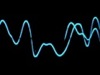
In general a wave will have an AC and a DC component, or a varying part summed with a constant part. When you shift down (or up) the graph of the varying (AC) part such that equal areas of that graph would be above and below the zero line the DC component is reduced to zero, and the amount you shifted the the wave by is it's DC component.
Now an AC mixer, or better said an AC couple mixer, will do that shifting process such that the resulting DC component will be zero.
For audio the DC component has no relevant information and usually it's even in the way and that is why it gets stripped off with AC coupling.
For control signals however DC usually is relevant, as a DC voltage going up could mean that an oscillator will put out a higher pitched voltage. At the same time you might want to modulate that pitch to get vibrato - this can be done by using a DC mixer.
Hope this clears it up a bit.
_________________
Jan
also .. could someone please turn down the thermostat a bit.
 |
|
|
Back to top
|
|
|
prinsen
Joined: Jul 21, 2008
Posts: 5
Location: Copenhagen
|
| Posted: Thu Sep 02, 2010 12:17 pm Post subject:
|
|
|
| Ian Wilson wrote: | Thanks Prinsen,
That's exactly what I'm struggling with. The difference between the two mixers is small but important and I don't understand why. I thought I was looking for a mixer - now I'm looking at whether I need an AC mixer, a DC mixer or both and that's puzzling me. |
You're welcome.
If what you need at the moment is to mix three oscillators and pass the mix onto your amp, then go for the AC coupled mixer. You can always build a DC mixer later. Summing amplifiers like the simple MFOS ones are cheap and easy to build.
Btw. if you look at the schematic for the MFOS VCO you'll see that there's a mixer summing the 1V/oct inputs and the Tune and Coarse pots, which is similar to ones we've been discussing. Note that there are no capacitors in series with the inputs. So... it's a DC mixer! |
|
|
Back to top
|
|
|
Captain Biscuits
Joined: Jun 11, 2010
Posts: 116
Location: Northampton, UK
|
| Posted: Sat Sep 04, 2010 3:36 pm Post subject:
|
|
|
Thanks to you both for your helpful replies.
I'm gradually getting much clearer (I think!).
As I understand it all of my oscillators are AC oscillating equally above and below zero V wheras the output from an ADSR generator will be a rising and falling DC voltage (and will all be at or above zero V). I'm trying to think of another control which would be DC and can only think of keyboards, gates and triggers (I guess triggers can be either). Are there more that I'm missing?
I've just seen Ray's new toy and was interested in his double mixer from one TL074 on the kludge board which would do me nicely. It will be my first foray into building on stripboard so should be interesting. I'll let you know how it goes! I don't have an 074 around but I'm hoping an 072 will do the trick. Lets see what sort of mess I can make of an innocent piece of stripboard!
Thanks again for the help
All the best,
Ian |
|
|
Back to top
|
|
|
blue hell
Site Admin
Joined: Apr 03, 2004
Posts: 24423
Location: The Netherlands, Enschede
Audio files: 297
G2 patch files: 320
|
| Posted: Sat Sep 04, 2010 3:49 pm Post subject:
|
|
|
You get the idea there alright 
TL074 has four opamps TL072 has two, the opmaps themselves are identical, just a packaging difference.
_________________
Jan
also .. could someone please turn down the thermostat a bit.
|
|
|
Back to top
|
|
|
varice

Joined: Dec 29, 2004
Posts: 961
Location: Northeastern shore of Toledo Bend
Audio files: 29
G2 patch files: 54
|
| Posted: Sat Sep 04, 2010 11:02 pm Post subject:
|
|
|
| Ian Wilson wrote: | | …As I understand it all of my oscillators are AC oscillating equally above and below zero V wheras the output from an ADSR generator will be a rising and falling DC voltage (and will all be at or above zero V). I'm trying to think of another control which would be DC and can only think of keyboards, gates and triggers (I guess triggers can be either). Are there more that I'm missing? … |
You would also want to use a DC mixer for LFO signals. In most cases, it is best to use a DC mixer for all control signals.
Also keep in mind that a pulse oscillator will generate an asymmetrical waveform around the zero volt level (creating an average DC offset) when it is set to any waveshape other than a 50/50 duty cycle. And VCOs can generate asymmetrical waveforms when they are frequency modulated with audio waves. So it may be handy to have an AC coupled mixer for the VCOs in this case and when using these signals mixed back into the VCOs for FM. If an audio signal used for FM has a DC offset, the signal will cause the modulated VCO to also change in the perceived pitch instead of just the timbre of the output. Waveshapers and other audio distortion modules can also create asymmetrical outputs if they have DC coupled outputs. Fortunately, many filter designs use AC coupling, so for the common subtractive synth patch of VCOs -> mixer -> VCF -> VCA, the DC mixer can be used. But if you don’t have AC coupling before the VCA and your audio signal is asymmetrical (has an average DC offset), it may cause undesirable clicks, pops, or thumps as the EG modulates the amplitude of the signal through the VCA.
_________________
varice |
|
|
Back to top
|
|
|
Don Erskine
Joined: Jun 17, 2010
Posts: 41
Location: UK
|
| Posted: Thu Sep 09, 2010 9:00 pm Post subject:
|
|
|
I intend to get several MFOS VCOs. They look very good on paper.
In an analogue Synth, there is no clear distinction between audio and control voltages. Below a certain frequency, (around 20Hz) you can't hear things, but a pulse will still contain harmonics that will be audible. You can't hear DC.
For example, an LFO at sub-audio frequencies might be used as a CV for Frequency Modulation (vibrato) or Pulse Width Modulation in a VCO. If the LFO frequency is increased, the same LFO is an audible oscillator.
Control voltage signals from things like ADSRs are usually positive going; if used to control a VCA, the VCA will have maximum attenuation when the CV is 0v. Some VCA designs will accept negative control voltages; in such cases a negative voltage control signal will attenuate or amplify and INVERT the audio signal.
Audio in a synth is typically up to 10 volts peak-to-peak (+/-5v DC). Control voltages are typically in the same range. So a Control Voltage varying over 10v used as a CV into a 1v/Octave VCO will sweep the VCO through 10 octaves.
Gates and triggers are usually positive-going pulses; going above about +2.5v triggers a device or turns it on (gates it).
There is no reason why a gate signal cannot be used as a Control Voltage as well, and often is. Conversely, a square wave (in fact, almost any wave) output from an LFO can be used to trigger an ADSR. When you realise that ANY voltage source can be potentially used as a control or gate voltage, you are able to do a lot more with a synthesiser.
There are reasons why you might want to mix DC with an oscillator waveform - for example, to set the clipping level in a waveshaper.
Synthesiser modules are designed so that no harm can be done by inputting these voltages into any input, though the results may not always be musical.
The important point is that an analogue VC synth is normally DC-coupled throughout. It's only when you feed the output signal into an external amp that you certainly want to filter out the DC and the audio amp will have a filtering capacitor on it's input to do that.
On rare occasions a large capacitor may be used in series on an audio input, to remove DC and low frequencies. In a synth, DC is more normally removed by offsetting it (mixing it) with DC of the opposite polarity. E.G. If a keyboard outputs +2v, it will CV a VCO to sound 2 octaves above the pitch it sounds at 0v. If -1v is mixed with this keyboard CV, the VCO will drop 1 octave, to 1 octave above the pitch it sounds at 0v.
Synth audio levels are much higher than in 'normal' audio, which is typically around 6-700mV RMS. (0dBm) in a studio. A synth will need to be attenuated before it is fed into ordinary audio equipment.
The outputs of the MFOS VCO have 1K resistors. These are there to protect the circuit if the outputs are short circuited. It sounds like you are hard-wiring these outputs together - A DC mixer is what you require to do the job properly. As the outputs are each potentially +/-5v, you need to attenuate the output or it will be distorted. Using an AC mixer on the output wouldn't do any harm though. |
|
|
Back to top
|
|
|
Captain Biscuits
Joined: Jun 11, 2010
Posts: 116
Location: Northampton, UK
|
|
|
Back to top
|
|
|
jordroid
Joined: Jan 17, 2010
Posts: 193
Location: ithaca, new york
|
| Posted: Fri Sep 17, 2010 12:33 pm Post subject:
|
|
|
If you are building either of the MFOS filters (which you should because they sound great) they each have a three input AC coupled mixer built in, pretty handy. You are right that you will want lots of mixing capability, Ray tends to include attenuators and mixers in convenient places in his modules, which reduces the need for dedicated mixers, but you will probably still be happy to have them.
Cheers. |
|
|
Back to top
|
|
|
Rojo
Joined: May 10, 2005
Posts: 14
Location: Boston
|
| Posted: Sat Sep 18, 2010 9:20 am Post subject:
|
|
|
| From this description, AC couplers sound like high pass filters. If that's how they behave, what might an AC coupler's response look like across low frequencies (say 0.1 Hz - 100 Hz)? |
|
|
Back to top
|
|
|
Don Erskine
Joined: Jun 17, 2010
Posts: 41
Location: UK
|
| Posted: Sat Sep 18, 2010 6:06 pm Post subject:
|
|
|
| Rojo wrote: | | From this description, AC couplers sound like high pass filters. |
That is exactly what a DC-blocking capacitor in an input network is.
The frequency response depends on the value of C and the input impedance of the rest of the input circuit, which is typically resistive.
This calculator will let you play with values for a simple RC network:
http://www.vk2zay.net/calculators/rc.php |
|
|
Back to top
|
|
|
blue hell
Site Admin
Joined: Apr 03, 2004
Posts: 24423
Location: The Netherlands, Enschede
Audio files: 297
G2 patch files: 320
|
| Posted: Sat Sep 18, 2010 7:00 pm Post subject:
|
|
|

_________________
Jan
also .. could someone please turn down the thermostat a bit.
|
|
|
Back to top
|
|
|
Captain Biscuits
Joined: Jun 11, 2010
Posts: 116
Location: Northampton, UK
|
| Posted: Sun Oct 17, 2010 12:16 pm Post subject:
|
|
|
Well, despite having only the scantest knowledge of what I'm doing I've managed to stripboard Ray's "Ultra Simple Mono Mixer" which I'm pretty chuffed with.
The only issue I had was with adjusting the gain. I had to seriously reduce the resistance of the feedback resistors. The headphone amp ones I took down from 100K to 4.7K before I got well out of headphone-crushingly-loud territory.
If I did it again I think I'd be tempted to use a couple of 20K pots to adjust the gain.
Dizzy with success I'll have a go at the AC mixers when I next get the chance.
Now I just need many many more patch cables |
|
|
Back to top
|
|
|
|

 Forum index » DIY Hardware and Software » MusicFromOuterSpace.com designs by Ray Wilson

