| Author |
Message |
Dr. K
Joined: Jan 15, 2020
Posts: 52
Location: wisconsin
|
 Posted: Wed Dec 11, 2024 5:24 pm Post subject:
8-Step Seq.---a few questions about a schematic Posted: Wed Dec 11, 2024 5:24 pm Post subject:
8-Step Seq.---a few questions about a schematic |
  |
|
I tried emailing the author directly, but the message was bounced back.
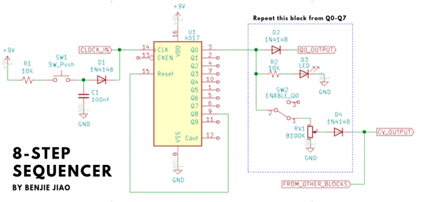
I'm hoping to build a "baby-8" sequencer, and this seemed to be the clearest schematic that I could find. I'm not a TOTAL novice--but no expert either.
The 2 questions are, on the left side of the schematic, what's the story with the push button that's connected to 9V, and then goes to the clock input? I'm assuming this is so that you can turn off the clock, and then advance the sequence using a push button, manually?
The other thing is, on the output (Q0, on this diagram), I'm curious what the Q0 (and higher Q's) are for. They would not be used for the control voltage--but I'm assuming to drive some other devices?
https://benjiaomodular.com/post/2021-04-09-8-step-sequencer/
| Description: |
|
| Filesize: |
181.71 KB |
| Viewed: |
38 Time(s) |
| This image has been reduced to fit the page. Click on it to enlarge. |
|
|
|
|
Back to top
|
|
 |
blue hell
Site Admin

Joined: Apr 03, 2004
Posts: 24396
Location: The Netherlands, Enschede
Audio files: 296
G2 patch files: 320
|
| Posted: Wed Dec 11, 2024 5:45 pm Post subject:
|
|
|
a) the idea would be manual stepping yes .. but the way it is done it'd be best to not connect a clock when doing manual steps .. and maybe add a resistor after the diode - to ground .. couple of k's.
b) the 4017 will first make q0 active .. a digital signal .. then q1 etc .. each q has a pot associated in the repeat block for setting a step amalog value
Then the q0_output and friends would give a pulse when the corresponding step is reached, which coud be used to trigger a percussive thing; then when you have a couple of those it would make a pattern .. could be pretty nice 
Or trigger a slower second sequencer on one of the steps
Or speed up the clock for one period, to make odd tempo changes
Or on an fm input to make a pich jump.
Or .. whatever .. it really is a nice to have thing!
Edits :
.. o .. and the CKEN input must be connected to something .. lemme see +9v here .. for it to work reliably enabled.
And then the clock input could use a diode and a resistor too, to be able to use clock and button simultaneously without angrying datasheets ... it'll probably work as is .. but it is just not .. erm .. not done
But best to build it .. to see where it - for you - works and where it does not
_________________
Jan
also .. could someone please turn down the thermostat a bit.
 |
|
|
Back to top
|
|
|
Dr. K
Joined: Jan 15, 2020
Posts: 52
Location: wisconsin
|
| Posted: Thu Dec 12, 2024 3:57 pm Post subject:
|
|
|
Thank you so much for the info! I've been moving towards building from scratch (vs. kits) and trying to learn as much along the way as possible. A sequencer will make all my noisy gizmos a lot more fun and musical.
So with your suggested mods (ie, tying the pin to +9, the assorted diodes/resistors), the sequencer should work? I already have a couple 555 an 40106 low freq. oscillators built up, so testing and running it should be no sweat.
One final thing, the voltages coming out of the CV should be sufficient to run an LED or two, for use with a homeade cheezy little vactrol? (some of my circuits already have LDRs--driving an LED with the sequencer would be a very easy first step).
Thank you again for the info. I intend to breadboard the circuit first (at least a couple of steps), but the internet being what it is, you frequently find serious errors. |
|
|
Back to top
|
|
|
blue hell
Site Admin
Joined: Apr 03, 2004
Posts: 24396
Location: The Netherlands, Enschede
Audio files: 296
G2 patch files: 320
|
| Posted: Thu Dec 12, 2024 4:54 pm Post subject:
|
|
|
Oh, oops (*)..
The CKEN is wrongly labeled in the schematic above .. looking at the data sheet of the 4017 ... it is a NOT EN actually and so it shoud be tied to ground to enable .. instead of what i had said before.
LED driving .. may not work to well with this setup .. the potmeter value might have to be lower .. depends on LED efficiency ... but 100k seems a bit much .. then also when the pot is at max the LED hangs directly on the IC .. which eh .. you know .. it will not break anything .. but a little series resistor might be a good idea there .. or at least be the decent thing to do .. 220 Ohm or so or maybe 390 ...
It will need experimentation .. at least .. for me it is too long ago to be fool proof sure
Or alternatively there would have to be buffering .. seems a bit of a waste though for the now really simple circuit .. anyway .. it would be possible to add a bunch of opamps ...
Edit : (*) the oops may stem from the fairchild data sheet which labels pin 13 as clock enable - which is wrong. The TI data sheet labels it as clock inhibit .. and this is what matches the schematic version of the internals and the given timing diagrams.
_________________
Jan
also .. could someone please turn down the thermostat a bit.
|
|
|
Back to top
|
|
|
Dr. K
Joined: Jan 15, 2020
Posts: 52
Location: wisconsin
|
| Posted: Sun Dec 15, 2024 5:34 pm Post subject:
|
|
|
Hmm, a buffer on the CV output? Would it require 8 buffers, or, because all the CVs are tied together, could you run just one buffer?
I'll have to look into how to do that. I'm assuming you mean using an op-amp, in unity gain configuration, just so the LED isn't loading the chip directly? Maybe a very common one, TLO72? Or, seeing as I'm planning an onboard clock made of a 40106, could I just run the CV into one of those, and take it's output to drive the LED?
Thanks again for the advice. I want to make a really good one, with maximum functionality. A good sequencer will be critical to taming all the other devices. |
|
|
Back to top
|
|
|
Dr. K
Joined: Jan 15, 2020
Posts: 52
Location: wisconsin
|
| Posted: Mon Dec 16, 2024 4:12 pm Post subject:
|
|
|
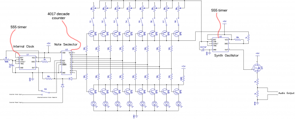
I've done some more reading, and was wondering if a CV configuration like this would be more suitable for the instance of driving LEDS for use in a vactrol. A transistor unity gain buffer? That should totally isolate the chip from the output, and the transistor would be suppllying the required current (if I understand the idea correctly).
Also, for the switches in the CV block of the diagram, when they are in the position shown, they will deliver the control voltage. But is the other pole supposed to be connecte dto the reset, so that particular step is skipped? If any of the steps are switched to reset, does that cut off the rest of the sequence, and start over with zero? Or does it simplyl skip that step, and move on to the next one? Or does the step exist in time, but without a voltage output?
| Description: |
|
| Filesize: |
182.88 KB |
| Viewed: |
52 Time(s) |
| This image has been reduced to fit the page. Click on it to enlarge. |
|
|
|
|
Back to top
|
|
|
PHOBoS

Joined: Jan 14, 2010
Posts: 5797
Location: Moon Base
Audio files: 709
|
| Posted: Mon Dec 23, 2024 6:17 pm Post subject:
|
|
|
| Dr. K wrote: | | I've done some more reading, and was wondering if a CV configuration like this would be more suitable for the instance of driving LEDS for use in a vactrol. A transistor unity gain buffer? That should totally isolate the chip from the output, and the transistor would be suppllying the required current (if I understand the idea correctly). |
yes kinda, but you'd have to wire them up differently then shown in that schematic. 
sequencing vactrols while having a useful range can be a pain but also give some really nice results.
How well things work depends a lot on the vactrol itself and the way it is used in a circuit.
Ideally you'd first want to create a control voltage and convert that to a suitable current for controlling the vactrol.
| Quote: | | Also, for the switches in the CV block of the diagram, when they are in the position shown, they will deliver the control voltage. But is the other pole supposed to be connecte dto the reset, so that particular step is skipped? |
The other pole of the switches does not seem to be connected to anything so if a switch is open and that step is active you simply won't get any voltage
during the duration that the step is active. The output is basically floating (would be 0V if it wasn't for the diode).
| Quote: | | If any of the steps are switched to reset, does that cut off the rest of the sequence, and start over with zero? Or does it simplyl skip that step, and move on to the next one? Or does the step exist in time, but without a voltage output? |
If you would connect it to the reset than it'll jump immediately back to the start as soon as that step becomes active. Using a individual switches
like this to set the sequence length is a method I personally prefer over using something like a rotary switch.
You can also connect switches between the outputs and the clock INH /EN pin which will hold the sequencer when that step is active until it gets
reset. This can be useful to create timed CV bursts. (you could use a switch per step and 1 extra switch to select between RST or CLK INH)
_________________
"My perf, it's full of holes!"
http://phobos.000space.com/
SoundCloud BandCamp MixCloud Stickney Synthyards Captain Collider Twitch YouTube |
|
|
Back to top
|
|
|
|

 Forum index » DIY Hardware and Software » Lunettas - circuits inspired by Stanley Lunetta