| Author |
Message |
austrohungaro
Joined: Dec 23, 2006
Posts: 42
Location: Barcelona (Spain)
Audio files: 1
|
 Posted: Tue Jul 08, 2008 3:22 am Post subject:
Two Phasers in a Box Posted: Tue Jul 08, 2008 3:22 am Post subject:
Two Phasers in a Box
Subject description: Can I use only one transformer to power both PCBs? |
  |
|
Hello
I moved my Krautrock Phaser to a new, bigger case. It is big enough to fit a Tau Phaser too, and I don't know if I can use only one transformer (830 mA) to power both PCBs.
I know I could build a +-15V Power Supply, but I already have populated the PCBs, and I'd hate to do de-soldering to remove all the redundant parts.
Is it recommended to power two PCBs from the output of a single transformer? Should I use two transformers?
Thanks
Genís |
|
|
Back to top
|
|
 |
jhaible
Joined: May 25, 2007
Posts: 2014
Location: Germany
Audio files: 24
|
Posted: Tue Jul 08, 2008 4:12 pm Post subject:
Re: Two Phasers in a Box
Subject description: Can I use only one transformer to power both PCBs? |
|
|
| austrohungaro wrote: | Hello
I moved my Krautrock Phaser to a new, bigger case. It is big enough to fit a Tau Phaser too, and I don't know if I can use only one transformer (830 mA) to power both PCBs.
I know I could build a +-15V Power Supply, but I already have populated the PCBs, and I'd hate to do de-soldering to remove all the redundant parts.
Is it recommended to power two PCBs from the output of a single transformer? Should I use two transformers?
Thanks
Genís |
You cannot simply connect the transformers to the AC inputs of two PCBs.
Here is what I'd try (should work, but is untested):
Build the Krautrock with on-board PSU, and the Tau without.
Then bring the +/-15V DC from the Krautrock over to feed the Tau.
The Krautrock *should* be able to carry the extra current, with its heatsinks and all. (But you have to check for yourself and ascertain that nothing gets too hot!). It won't work the other way round (AC on TAU, DC on Krautrock), because on the TAU there is no room for big heatsinks.
Let us know when it works!
JH.
_________________
"I tell you the truth, if anyone says to this mountain, 'Go, throw yourself into the sea,' and does not doubt in his heart but believes that what he says will happen, it will be done for him. Therefore I tell you, whatever you ask for in prayer, believe that you have received it, and it will be yours." (Mk 11,23f) |
|
|
Back to top
|
|
|
Dave Kendall

Joined: May 26, 2007
Posts: 421
Location: England
Audio files: 3
|
| Posted: Wed Jul 09, 2008 11:03 am Post subject:
|
|
|
Hi.
Hope this is not too OT - it's about 2 JH pcbs in one box, one of which is a TAU, but there's a couple of things I'm not sure about..... 
| Quote: | | You cannot simply connect the transformers to the AC inputs of two PCBs |
I was hoping to be able to power both the Triple Chorus and a Tau Phaser from the same transformer, in a 1U rack case. I found a neat low profile 18-0-18 AC toroidal which is rated at 15VA, which if I've got it right, should put out around 290 mA rectified. (hopefully that would be enough for both devices)
In another thread on the KenStone designs sub-forum, http://electro-music.com/forum/topic-27075.html Ken suggested that it would be possible to run both a CGS14 http://www.cgs.synth.net/modules/cgs14_psu.html and a CGS66
http://www.cgs.synth.net/modules/cgs66_psu.html from the same 18-0-18 75VA transformer.
I have an EFM 3501 (similar to the CGS66 - the docs are in the thread above) and was going to attempt that soon for the modular. But that sounds like I'd be attempting what isn't possible with the 2 JH boards.........
I had assumed that the power conditioning/regulator sections of the JH boards did roughly the same sort of job as the 2 CGS boards, but with lower capacity capacitors for example - 470uF vs. 2200uF +.
I've probably misunderstood something here - I'm very green as far as PSUs are concerned....' ' Does anyone know what the differences are between running the 2 CGS PSU boards off one transformer, and running the 2 JH boards? I guess omitting the on-board regulation and running both JH boards off ±15V with a separate PSU like the CGS boards would work, but it would be nice to be able to use the PSU regulation on the JH boards themselves if possible. ' Does anyone know what the differences are between running the 2 CGS PSU boards off one transformer, and running the 2 JH boards? I guess omitting the on-board regulation and running both JH boards off ±15V with a separate PSU like the CGS boards would work, but it would be nice to be able to use the PSU regulation on the JH boards themselves if possible.
Would upgrading some components on one of the JH boards, and taking a ±15V feed to the other with its PSU/regulator components omitted work at all?
Sorry for all the questions, but it has me puzzled. PSUs going bang I guess would not be much fun...........
(BTW, The tau is due for final assembly and testing very soon. Have received the last few parts ready to put in... YAY! ....... )
cheers,
Dave |
|
|
Back to top
|
|
|
jhaible
Joined: May 25, 2007
Posts: 2014
Location: Germany
Audio files: 24
|
| Posted: Wed Jul 09, 2008 12:54 pm Post subject:
|
|
|
Speaking of my PCBs only, there are two options:
Either
(1) give every PCB its own transformer & fuses and use the on-board PSU,
which may not be shared between PCBs,
or
(2) power several PCBs from a +/-15V DC PSU (omitting on-board PSU), which can be shared between several PCBs.
A subset of (2) is to use the on-board PSU of one PCB and feed the +/-15V DC from this board to the other boards (these, without on-board PSU). But for this, you need better heat sinking than is normally provided, so you have to find a solution for attaching (insulated!!) heat sinks to the voltage regulators of that first PCB that has the PSU.
You *may* also have to increase the 470uF caps at some point (depending on teh number of modules, socondary of your transformer, etc.)
But the 470u are oversized already (providing some reserve for loosing capacitance from ageing).
If you try anything like that, you should know exactly what you're doing.
If you don't - how much is a small AC wallwart, really? You probably get 3 or 4 wallwarts for the price of a good toroidal transformer, fuse holders, power switch, and what else you need for bulding the mains side of your own PSU.
JH.
_________________
"I tell you the truth, if anyone says to this mountain, 'Go, throw yourself into the sea,' and does not doubt in his heart but believes that what he says will happen, it will be done for him. Therefore I tell you, whatever you ask for in prayer, believe that you have received it, and it will be yours." (Mk 11,23f) |
|
|
Back to top
|
|
|
austrohungaro
Joined: Dec 23, 2006
Posts: 42
Location: Barcelona (Spain)
Audio files: 1
|
|
|
Back to top
|
|
|
blue hell
Site Admin

Joined: Apr 03, 2004
Posts: 24468
Location: The Netherlands, Enschede
Audio files: 297
G2 patch files: 320
|
|
|
Back to top
|
|
|
austrohungaro
Joined: Dec 23, 2006
Posts: 42
Location: Barcelona (Spain)
Audio files: 1
|
|
|
Back to top
|
|
|
Cat-A-Tonic
Joined: Mar 24, 2008
Posts: 42
Location: Yokohama, Japan
|
| Posted: Thu Jul 10, 2008 3:32 pm Post subject:
|
|
|
That is GORGEOUS!
can't wait to see it with knobs on.
I wish I had access to a printshop.
The process of such mediums is alot of fun when you get rolling. |
|
|
Back to top
|
|
|
jhaible
Joined: May 25, 2007
Posts: 2014
Location: Germany
Audio files: 24
|
| Posted: Fri Jul 11, 2008 3:12 am Post subject:
Re: Question about Tau's CV THRU and Krautrock possible CV I |
|
|
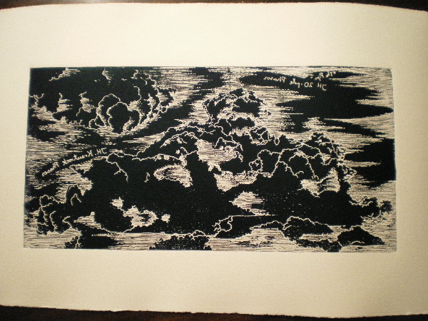
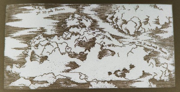
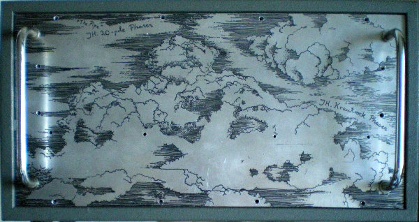
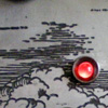
| austrohungaro wrote: | | I am drilling the panel. It has been etched by my friend who is into engraving/printing. He did a panel with clouds for my Two Phasers case. |
Absolutely cool frontpanel!
*Please* put a picture of this in my "Pictures" thread as well, once this is finished!
| Quote: | This is my guess:
From Tau's CV OUT jack -> CV -> to Krautrock's AMOUNT ???
From Tau's CV IN jack -> GROUND -> to Krautrock's SIGNAL GND ???
Is it correct? |
I have my doubts about the two CVs matching together nicely.
Both Phasers have very nonlinear CV response, and different CV range for their cores.
JH.
_________________
"I tell you the truth, if anyone says to this mountain, 'Go, throw yourself into the sea,' and does not doubt in his heart but believes that what he says will happen, it will be done for him. Therefore I tell you, whatever you ask for in prayer, believe that you have received it, and it will be yours." (Mk 11,23f) |
|
|
Back to top
|
|
|
austrohungaro
Joined: Dec 23, 2006
Posts: 42
Location: Barcelona (Spain)
Audio files: 1
|
| Posted: Sun Jul 13, 2008 5:25 am Post subject:
Re: Question about Tau's CV THRU and Krautrock possible CV I |
|
|
| jhaible wrote: |
I have my doubts about the two CVs matching together nicely.
Both Phasers have very nonlinear CV response, and different CV range for their cores.
JH. |
Schade!
Anyway, I posted a picture of the finished case on the "Photos of what you've built..." thread (http://www.electro-music.com/forum/post-195588.html#195588).
My Krautrock Phaser is not working perfect:
- Bypass led does not light (but Bypass Switch works!)
- 3rd lightbulb on panel does not light.
I have checked the board and as far as I can see, there's no cold solder, bad joint... I don't know if my SMD soldering was good (I'm not sure of my soldering in general). I don't know what can it be. Looks like two different problems, as LED uses +15 rail and LAMP -15. If I am right, they do not share parts, circuit paths...
I have measured DC on LED and LAMP
LED gets around +14.80
LAMP gets around -15.40 when everythnig disconnected.
If I connect the pots and measure ground from Ciurcuit's Ground it goes up and down. Can't be very exact on readings because my meter is maybe too crap, but it goes from 0 to -15.40
If I measure from pin to pin it reads 15.50
Well, I'll cross my fingers, as I am finishing the 20-pole Phaser... I guess leds won't light... |
|
|
Back to top
|
|
|
jhaible
Joined: May 25, 2007
Posts: 2014
Location: Germany
Audio files: 24
|
| Posted: Sun Jul 13, 2008 10:19 am Post subject:
Re: Question about Tau's CV THRU and Krautrock possible CV I |
|
|
| austrohungaro wrote: |
I have measured DC on LED and LAMP
LED gets around +14.80
|
LED should never have much more than 2 V (depending on its colour).
If you have more, it's probably soldered in backward, and quickly destroyed.
JH.
_________________
"I tell you the truth, if anyone says to this mountain, 'Go, throw yourself into the sea,' and does not doubt in his heart but believes that what he says will happen, it will be done for him. Therefore I tell you, whatever you ask for in prayer, believe that you have received it, and it will be yours." (Mk 11,23f) |
|
|
Back to top
|
|
|
austrohungaro
Joined: Dec 23, 2006
Posts: 42
Location: Barcelona (Spain)
Audio files: 1
|
| Posted: Sun Jul 13, 2008 11:04 am Post subject:
Re: Question about Tau's CV THRU and Krautrock possible CV I |
|
|
| jhaible wrote: |
LED should never have much more than 2 V (depending on its colour).
If you have more, it's probably soldered in backward, and quickly destroyed.
JH. |
OK. LED works now. I think I entered a bad karma loop reversing dead leds and killing reversed leds...
Now, I'm going to test the lughtbulb is OK, not dead, and the wiring.
Danke! |
|
|
Back to top
|
|
|
austrohungaro
Joined: Dec 23, 2006
Posts: 42
Location: Barcelona (Spain)
Audio files: 1
|
| Posted: Sun Jul 13, 2008 2:35 pm Post subject:
Lightbulb |
|
|
I have tried everything
Finally I have changed lamp AND lampholder and now it lights BUT it is always ON, it does not go up and down as the other two lamps on board, so... Can it be something about Q2 or Q3? I don't know who does what and I have no idea of how to measure it... |
|
|
Back to top
|
|
|
jhaible
Joined: May 25, 2007
Posts: 2014
Location: Germany
Audio files: 24
|
| Posted: Mon Jul 14, 2008 12:03 am Post subject:
Re: Lightbulb |
|
|
| austrohungaro wrote: | I have tried everything
Finally I have changed lamp AND lampholder and now it lights BUT it is always ON, it does not go up and down as the other two lamps on board, so... Can it be something about Q2 or Q3? I don't know who does what and I have no idea of how to measure it... |
Ok, I can explain how the lamp driver circuit works:
Q2 and Q3 form an inverting amplifier (think "inverting opamp" - it's not the same, but actually quite similar).
Q2 provides a lot of voltage gain. Q3 is just an emitter follower to provide enough current. The base of Q2 is the "op amps's" inverting input. The non-inverting input is not actually there - but D9, D10, D11 at the emitter of Q2 act as if you had a non-inverting input at aroud -2.3V. That's your (slightly negative) reference voltage for the inverting amplifier.
The Inverting amplifier is built with R23 and R32 providing a feedback loop around the amp.
R31 limits the amp's output current and keeps part of the heat away from Q3.
JH.
_________________
"I tell you the truth, if anyone says to this mountain, 'Go, throw yourself into the sea,' and does not doubt in his heart but believes that what he says will happen, it will be done for him. Therefore I tell you, whatever you ask for in prayer, believe that you have received it, and it will be yours." (Mk 11,23f) |
|
|
Back to top
|
|
|
austrohungaro
Joined: Dec 23, 2006
Posts: 42
Location: Barcelona (Spain)
Audio files: 1
|
|
|
Back to top
|
|
|
jhaible
Joined: May 25, 2007
Posts: 2014
Location: Germany
Audio files: 24
|
Posted: Wed Jul 16, 2008 12:14 pm Post subject:
Re: Lightbulb
Subject description: Alles ist gut |
|
|
| austrohungaro wrote: | It was Q2. It was dead or faulty, I don't know, but I have replaced it and now everythings works fine, and my Krautrock Phaser not only sounds great, it also looks great!
Vielen Dank!
Now it's time to finish the 20-pole Phaser, and try to power it from the Krautrock's power supply... |
Glad it works!
And, repeating myself, that front panel is *so* cool!
JH.
Now playing: Tori Amos, Bouncing off Clouds.
_________________
"I tell you the truth, if anyone says to this mountain, 'Go, throw yourself into the sea,' and does not doubt in his heart but believes that what he says will happen, it will be done for him. Therefore I tell you, whatever you ask for in prayer, believe that you have received it, and it will be yours." (Mk 11,23f) |
|
|
Back to top
|
|
|
austrohungaro
Joined: Dec 23, 2006
Posts: 42
Location: Barcelona (Spain)
Audio files: 1
|
| Posted: Thu Jul 17, 2008 2:57 am Post subject:
Re: Lightbulb |
|
|
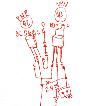
It was not easy for me to check that. I have no knowledge of electronics. I made a drawing of the signal path to understand what to test, transistors legs, CBE, EBC, NPN, PNP...
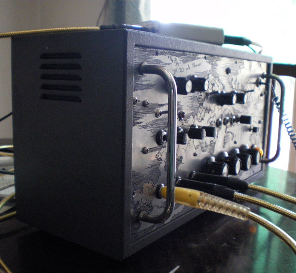
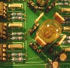
Also, I have noticed that the regulator's heatsinks get quite hot, in particular LM317's. Not that I got hurt when I touched it, but I don't know if I should find bigger ones before trying to feed the Tau board from the Krautrock's.
Another thing... MOD pot only seems to affect the sound when it's almost fully clockwise. Is that behaviour considered 'normal'?
Pictures of my drawings (so you can laugh) and my heatsinks follow.
| Description: |
|
| Filesize: |
37.11 KB |
| Viewed: |
15022 Time(s) |
|
| Description: |
|
| Filesize: |
23.28 KB |
| Viewed: |
15022 Time(s) |

|
|
|
|
Back to top
|
|
|
austrohungaro
Joined: Dec 23, 2006
Posts: 42
Location: Barcelona (Spain)
Audio files: 1
|
|
|
Back to top
|
|
|
|

 Forum index » DIY Hardware and Software » Jürgen Haible designs