| Author |
Message |
thepaddiscuile
Joined: Jul 11, 2007
Posts: 28
Location: ireland
|
 Posted: Sat Sep 02, 2017 5:59 am Post subject:
simple linear tri vco for drum circuits Posted: Sat Sep 02, 2017 5:59 am Post subject:
simple linear tri vco for drum circuits
Subject description: Simple linear vco ? |
  |
|
Hey everyone..
by any chance has anyone schematics of a low parts count vco that accepts bipolar cv and outputs a bipolar waveform.. I want to build up a drum voice on +-12v so im looking for a low parts count linear pitch response triangle wave vco.
The reason I need a vco that responds to a bipolar cv is because I want to use my existing modular lfos or whatever to control the cv of the linear vco..
OR Is it possible to bias an ac control voltage to ground at the negative peak of the waveform, so that I could use the classic schmitt trigger, integrator vco which only accepts positive supply for cv ? that might be another way to skin the cat.
Cheers
Pat |
|
|
Back to top
|
|
 |
gabbagabi

Joined: Nov 29, 2008
Posts: 652
Location: Berlin by n8
Audio files: 23
|
| Posted: Sun Sep 03, 2017 2:32 am Post subject:
|
|
|
hi,
thru_ Zero VCO's are able to process bipolar CV
otherwise u could rectify the cv, to do this u could use the MS20 Saw to tri wavesshaper, there is also one from tadej boziko or a more accurate one from yusynth. in fact they are full wave rectifier but we use them widely as saw2tri waveshaper.
And of course you can add an offset to any CV to move it into the positive Zone.
more details on demand 
cheers, gabbagabi |
|
|
Back to top
|
|
|
thepaddiscuile
Joined: Jul 11, 2007
Posts: 28
Location: ireland
|
| Posted: Sun Sep 03, 2017 7:44 am Post subject:
|
|
|
I took a look at dc level shifters and tested this one from doepfer called cv mixer with offset function, on the diy page
http://www.doepfer.de/DIY/a100_diy.htm
Got it to work on a computer simulation but the gains are low and according to his brief on the circuit, increasing the 100k resistor value in the feedback path of the summing amp should produce higher gain. but in my simulation it actually decreases the gain.. If I lower the value to 10k it actually increases the gain..Might be a typo on Doepfers behalf ??
Thru vco's are cool but much to complicated for my needs in a simple drum vco..
I think with this dc offset circuit above..I can use any vco that looks for a dc control voltage only..
Id still perfer a vco that is low parts count and can be cv'd with +-5v signals |
|
|
Back to top
|
|
|
PHOBoS

Joined: Jan 14, 2010
Posts: 5873
Location: Moon Base
Audio files: 709
|
|
|
Back to top
|
|
|
gabbagabi
Joined: Nov 29, 2008
Posts: 652
Location: Berlin by n8
Audio files: 23
|
|
|
Back to top
|
|
|
thepaddiscuile
Joined: Jul 11, 2007
Posts: 28
Location: ireland
|
| Posted: Sun Sep 03, 2017 9:39 am Post subject:
|
|
|
| PHOBoS wrote: | Unless the VCO CV input range is larger than your CV signal you shouldn't need any gain at all.
If you do need gain then increasing R5 or R7 should indeed work. Personally I would increase R7. |
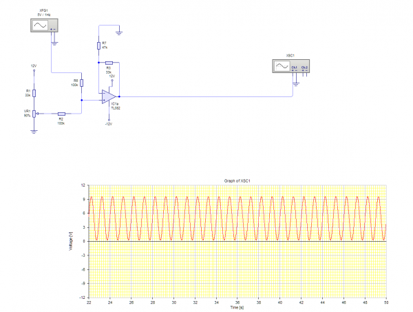
In the simulation I powered the opamps with +-12v and simulated a +-5v sinewave as the input cv to the summing opamp..
With the standard 100k resistors doepfer mentions as the feedback resistors I only get about a 2 volt positive waveform at the output.
I did try increasing both the feedback resistors to even 1 M.. but it has the opposite effect of actually lowering the gain..
I checked and triple checked the schematic in the simulation and unless I decrease the resistors I see no net gain.. |
|
|
Back to top
|
|
|
thepaddiscuile
Joined: Jul 11, 2007
Posts: 28
Location: ireland
|
| Posted: Sun Sep 03, 2017 9:43 am Post subject:
|
|
|
| g.gabba wrote: | hm,
i need to understand ur needs better.
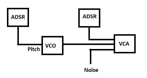
The way iam doing drums is like in the attached blockdiagram.
there i dont have a need for osc that can work with negative cv.
may u have a blockdiagram of what u are planning to do a bit more in detail?
for the tri vco - do u work with opamps or logic, which kind of power supply u are using? single/dual/12V/15V ? |
Yes this is how I am implementing the drums, but in order to modulate the drum vco cv with my modular vco's which would be +-5v I want to bias the negative portion of the modular vco's output to ground.. Assuming that I use a vco that is simpler to build running of a +v dc cv only..
I hope this explains it better.. |
|
|
Back to top
|
|
|
PHOBoS
Joined: Jan 14, 2010
Posts: 5873
Location: Moon Base
Audio files: 709
|
| Posted: Sun Sep 03, 2017 9:59 am Post subject:
|
|
|
| thepaddiscuile wrote: | | With the standard 100k resistors doepfer mentions as the feedback resistors I only get about a 2 volt positive waveform at the output. |
Something somewhere is wrong with the simulation. With all values 100K the output should be identical to the input.
At least when you leave out the offset resistor (=R8 in the doepfer schematic) which I think should be 240K for what
you want if it is connected to +12V. It is odd that it says 33K in the doepfer schematic although it doesn't mention what
voltage it is connected to. A 33K resistor together with the 100K will give a gain of 3x so if that is connected to +12v
the opamp just clips the signal. That could actually explain why you get the results you have and why lowering the gain
seems to help.
edit: gain of 3x was calculated without the potentiometer and input resistor
_________________
"My perf, it's full of holes!"
http://phobos.000space.com/
SoundCloud BandCamp MixCloud Stickney Synthyards Captain Collider Twitch YouTube
Last edited by PHOBoS on Sun Sep 03, 2017 10:22 am; edited 1 time in total |
|
|
Back to top
|
|
|
thepaddiscuile
Joined: Jul 11, 2007
Posts: 28
Location: ireland
|
| Posted: Sun Sep 03, 2017 10:07 am Post subject:
|
|
|
Whoops.. 
I had the negative rail of the opamp mistakenly powered from 12v, I forgot to type in -12v as the power supply..
A 47k limiting resistor for R8 gives my a perfect 10v positive sine now.. |
|
|
Back to top
|
|
|
PHOBoS
Joined: Jan 14, 2010
Posts: 5873
Location: Moon Base
Audio files: 709
|
| Posted: Sun Sep 03, 2017 10:15 am Post subject:
|
|
|
well that helps, good thing it is just a simulation 
47K seems low but I calculated without a pot which would act as a voltage divider. If both have a value of 47K it would result
in half the voltage so 6V a bit more than needed but depending on how good the software is this could actually be correct.
So you could just connect a resistor from +12V directly to the inverting input of O1 which I think should be around 240K.
Unless you want the offset level to be adjustable of course.
_________________
"My perf, it's full of holes!"
http://phobos.000space.com/
SoundCloud BandCamp MixCloud Stickney Synthyards Captain Collider Twitch YouTube |
|
|
Back to top
|
|
|
thepaddiscuile
Joined: Jul 11, 2007
Posts: 28
Location: ireland
|
| Posted: Sun Sep 03, 2017 10:45 am Post subject:
|
|
|
Yeah.. I suppose I will need the offset just because in the real world some of the vcos and lfos might be slightly beefier than +-5v.
Especially with a drum circuit ,I wouldn't want a waveform sitting above ground somewhere because It will alter the base frequency of the vco when it enters the cv input.
Now im just thinking can I simplify the doepfer schematic to use just one side of the opamp.. I don't need the inverting output..Just the mirrored and shifted positive going waveform.
Can you use the second opamp as both the summing mixer with offset and a non inverting output too ? |
|
|
Back to top
|
|
|
gabbagabi
Joined: Nov 29, 2008
Posts: 652
Location: Berlin by n8
Audio files: 23
|
| Posted: Sun Sep 03, 2017 11:19 am Post subject:
|
|
|
really sry.
but iam confused here 
do we talking about a kind of mixer for mixing the LFO the adsr and a offset together to feed it in the linear vco?
another question, do you already have the vco? |
|
|
Back to top
|
|
|
thepaddiscuile
Joined: Jul 11, 2007
Posts: 28
Location: ireland
|
| Posted: Sun Sep 03, 2017 3:13 pm Post subject:
|
|
|
the mixer we have discussed here.. will only be used to convert my modulars waveforms to positive going only.. and other signals for example envelopes will not be used with this circuit because they are already positive going..they will be sent directly to the vco cv input..
I have used this vco before..its a basic integrator/schmitt trigger..
This is what I might use again but with the above circuit summed to the cv input stage..
http://www.tradeofic.com/Circuit/3617-LINEAR_TRIANGLE_SQUARE_WAVE_VCO.html |
|
|
Back to top
|
|
|
thepaddiscuile
Joined: Jul 11, 2007
Posts: 28
Location: ireland
|
|
|
Back to top
|
|
|
Grumble
Joined: Nov 23, 2015
Posts: 1319
Location: Netherlands
Audio files: 30
|
| Posted: Sun Sep 03, 2017 9:55 pm Post subject:
|
|
|
problem with this configuration is that the amplitude of the sinewave at the output will vary with the position of the offset potentiometer.
_________________
my synth |
|
|
Back to top
|
|
|
gabbagabi
Joined: Nov 29, 2008
Posts: 652
Location: Berlin by n8
Audio files: 23
|
| Posted: Mon Sep 04, 2017 4:03 am Post subject:
|
|
|
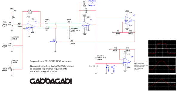
the osc u have choosen is also my first choice for tri core osc.
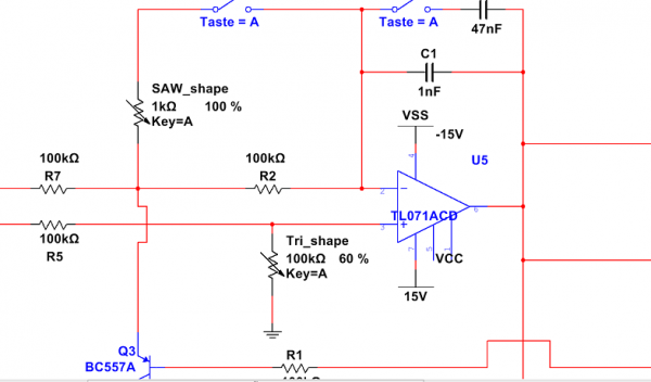
i attatched a schematic of how i would do it. Only 4 OPamps so u can use a quad, and a little Variety on the Outputwaveform by distorting the Triangle.
The core does work with negative Voltage (by using a PNP Transistor), so u can use a inverting summer for mixing ur CV's. U dont need to pre-offset ur cv before.
from my experience i would do the resistors before the Modulation-Sensivity-Pots even higher to get more adjustebility, cos normally i apply only very small amount of modulation when it comes to drums
edit: pic2, there is even a little Hack i found in a elektor book on how to get a saw out of it
| Description: |
|
| Filesize: |
88.44 KB |
| Viewed: |
331 Time(s) |
| This image has been reduced to fit the page. Click on it to enlarge. |
|
| Description: |
|
| Filesize: |
39.99 KB |
| Viewed: |
278 Time(s) |
| This image has been reduced to fit the page. Click on it to enlarge. |
|
|
|
|
Back to top
|
|
|
thepaddiscuile
Joined: Jul 11, 2007
Posts: 28
Location: ireland
|
| Posted: Mon Sep 04, 2017 7:13 am Post subject:
|
|
|
that's pretty cool..
Thats how I would have done it too with the summing stage but I didn't know about the Pnp trick.. So with a pnp instead of an npn you can use negative voltages ? Why have you tied the frequency pot to ground instead of a negative voltage if that's the case.. I would assume it would give you more range if it were tied to ground.
That sine shaper schematic I have used myself before.. Works great although I could never get a proper sine from it.. But close enough for music purposes..
Thanks for sharing your ideas.. |
|
|
Back to top
|
|
|
thepaddiscuile
Joined: Jul 11, 2007
Posts: 28
Location: ireland
|
| Posted: Mon Sep 04, 2017 7:16 am Post subject:
|
|
|
| Grumble wrote: | | problem with this configuration is that the amplitude of the sinewave at the output will vary with the position of the offset potentiometer. |
True but that would be a set and forget resistor..
I used it in the schematic to determine what resistor I would need to get 5v bipolar waveforms sitting around ground.. |
|
|
Back to top
|
|
|
gabbagabi
Joined: Nov 29, 2008
Posts: 652
Location: Berlin by n8
Audio files: 23
|
| Posted: Mon Sep 04, 2017 8:23 am Post subject:
|
|
|
yes, with the trick-pnp u can, and must use negative CV.
so if u feed in a positive voltage in the inverting summer it comes out negative at the output. Than this negative voltage is going to the vco. So if u would tie the freq pot to -15V, after the middle position there would be a positive CV coming out of the summer, in that case the vco would stop.
regarding the shaper if ur incoming triangle is 10Vpp and well balanced around 0V u use a combination of resistors that have the relation of 1:6,8 u should get something similar to sine out. i use normally 10k/68k, yusynth for example uses 22k/150k. But of course it could never be a real pure sine.
Last edited by gabbagabi on Mon Sep 04, 2017 1:05 pm; edited 1 time in total |
|
|
Back to top
|
|
|
thepaddiscuile
Joined: Jul 11, 2007
Posts: 28
Location: ireland
|
| Posted: Mon Sep 04, 2017 12:33 pm Post subject:
|
|
|
The vco will only work with positive or negative voltage but not both ?
Then this does not allow a modular vco with+-5v waveforms to modulate the cv.. |
|
|
Back to top
|
|
|
gabbagabi
Joined: Nov 29, 2008
Posts: 652
Location: Berlin by n8
Audio files: 23
|
| Posted: Mon Sep 04, 2017 1:21 pm Post subject:
|
|
|
the vco is working only with negative cv, but u apply positive voltages to the iverting summer which then provides the needed negative voltages to the vco.
if u set with the freq pot 10V and apply the full 10Vpp from ur lfo the CV is swinging from 5V to 15V or if u set 5V at the freq pot it will swing from 0V to 10V. Then everything inverted by the inverting summer. |
|
|
Back to top
|
|
|
|

 Forum index » DIY Hardware and Software » Developers' Corner