| Author |
Message |
synaesthesia

Joined: May 27, 2014
Posts: 291
Location: Germany
Audio files: 85
|
 Posted: Sat Mar 30, 2019 4:40 am Post subject:
Voltage controlled Resistance Posted: Sat Mar 30, 2019 4:40 am Post subject:
Voltage controlled Resistance
Subject description: simple circuit with DIY vactrol |
  |
|
Very often I wished that I could control a potentiometer in a Lunetta circuit with a voltage controlled resistor. Of course, you immediately think about vactrols. Commercially available vactrols are nice but expensive. A simple do-it-yourself vactrol is easy to make, but the non-linearities of the LED and the LDR make it really hard to control.
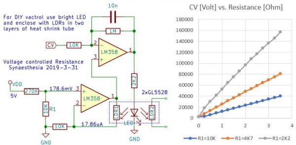
This is a circuit that I am using to tame those non-itineraries and create a well-behaving voltage controlled resistance. The DIY vactrol consists of a bright flat-head LED and two GL5528 LDRs in a heat shrink tube package. I chose an amber LED simply because I happened to have those available. The reason for using a flathead type LED is that it nicely fits next to two GL55xx LDRs in a 5mm shrink tube when you bend away the two wires right at the body. Two layers of black shrink tube are required to seal the package properly, so I wrapped the result in another piece of 6mm shrink tube. I tried several LDRS like GL5516, GL5528, GL5539, GL5549 and found the GL5516 and GL5528 types work better, because I do not need the high resistance when dark that the other types provide.
Resistor R1 forms a simple voltage divider with LDR1 and is used to feed back the current voltage from the divider to the opamp, which then regulates the voltage at the LED. You can adjust the range of the controllable resistance by changing the value of R1 and the Vdd voltage that you apply. I am using 5 Volts Vdd here. The 1M resistor and the small capacity at the opamp dampen the regulation a bit. The second LDR2 is illuminated by the same LED and thus has approximately the same resistance as LDR1. This LDR can be used to replace a resistor or potentiometer in your circuit.
The nice feature of this circuit is that it can replace a resistor or potentiometer with two floating terminals, for example in a filter, and make it voltage controllable. The response of the resistance to the control voltage is a bit delayed, because the LDRs respond rather slow, but more than fast enough to use this circuit with a voltage coming from an LFO.
My control voltages are typically in the range of 0 to 3.5 Volts, because I used LM358s at 5 Volts frequently, so that is the range that I measured. The image below shows the circuit and the resulting resistance at LDR2 for control voltages in the range of 0 to 3.5 Volts. Quite neat, isn't it?
| Description: |
|
| Filesize: |
43.09 KB |
| Viewed: |
569 Time(s) |
| This image has been reduced to fit the page. Click on it to enlarge. |
|
|
|
|
Back to top
|
|
 |
PHOBoS

Joined: Jan 14, 2010
Posts: 5908
Location: Moon Base
Audio files: 709
|
|
|
Back to top
|
|
|
synaesthesia
Joined: May 27, 2014
Posts: 291
Location: Germany
Audio files: 85
|
| Posted: Sat Mar 30, 2019 8:46 am Post subject:
|
|
|
| I think the correct name is straw hat. Rounded top, but for wide angles. |
|
|
Back to top
|
|
|
Grumble
Joined: Nov 23, 2015
Posts: 1320
Location: Netherlands
Audio files: 30
|
|
|
Back to top
|
|
|
synaesthesia
Joined: May 27, 2014
Posts: 291
Location: Germany
Audio files: 85
|
|
|
Back to top
|
|
|
Grumble
Joined: Nov 23, 2015
Posts: 1320
Location: Netherlands
Audio files: 30
|
| Posted: Sun Mar 31, 2019 1:19 pm Post subject:
|
|
|

This way you only need one opamp and it is linear (for as much as the two ldr’s are the same and at equal distance from the light)
_________________
my synth |
|
|
Back to top
|
|
|
piedwagtail

Joined: Apr 15, 2006
Posts: 297
Location: shoreditch
Audio files: 3
|
|
|
Back to top
|
|
|
Grumble
Joined: Nov 23, 2015
Posts: 1320
Location: Netherlands
Audio files: 30
|
| Posted: Sun Mar 31, 2019 10:48 pm Post subject:
|
|
|
An improvement could be to mount each LDR to its own LED and place the LED's in series.
_________________
my synth |
|
|
Back to top
|
|
|
|

 Forum index » DIY Hardware and Software » Lunettas - circuits inspired by Stanley Lunetta