| Author |
Message |
skrasms
Joined: Feb 21, 2008
Posts: 121
Location: Portland, OR
|
 Posted: Mon Mar 10, 2008 8:09 pm Post subject:
Protecting A/D Pins on a Micro Posted: Mon Mar 10, 2008 8:09 pm Post subject:
Protecting A/D Pins on a Micro
Subject description: My CV Inputs need some protection |
  |
|
Is there a good, simple circuit for protecting the A/D input pins on a microcontroller? For example, with the dsPIC30F4013 the maximum allowed input voltage to any pin is Vdd + 0.3, and the minimum is Vss - 0.3. I would like my circuit to be robust enough that if someone manages to hook in +/- 10V on accident, that the result will not fry the micro (I tried +10 for a moment and it did, by the way). I thought I could use a simple diode clamp setup, but since turn-on voltages are in the range of 0.6V it does not seem as easy as just single diodes.
I am looking to leave the input signal unchanged except for having a set maximum and minimum, so I would prefer to leave out any kind of voltage division or scaling.
Any help is greatly appreciated. |
|
|
Back to top
|
|
 |
widdly
Joined: Jun 25, 2007
Posts: 268
Location: singapore
G2 patch files: 2
|
| Posted: Tue Mar 11, 2008 10:09 am Post subject:
|
|
|
I've been thinking about this problem recently too (for adding CV inputs to the electric druid VC LFO). Perhaps you could use a pair of zener diodes to limit the input to a certain voltage. Then use an op-amp to attenuate the input voltage down to the range you are interested in.
.....hmmm I just noticed you mentioned no voltage scaling of the input in your post. I guess another amplifier before the zener diodes might work.
Last edited by widdly on Thu Aug 05, 2010 10:19 pm; edited 1 time in total |
|
|
Back to top
|
|
|
blue hell
Site Admin

Joined: Apr 03, 2004
Posts: 24496
Location: The Netherlands, Enschede
Audio files: 298
G2 patch files: 320
|
| Posted: Tue Mar 11, 2008 10:22 am Post subject:
|
|
|
Use Schottky diodes (like BAT85 maybe) and a current limiting resistor. The Schottky diodes will clamp at a lower voltage and they are faster as well.
Be sure to check the PIC data sheets for the effect that an input resistor will have on the AD sampling time needed, as extra resistance means it will take longer to charge up the internal sampling capacitor.
_________________
Jan
also .. could someone please turn down the thermostat a bit.
 |
|
|
Back to top
|
|
|
State Machine
Janitor


Joined: Apr 17, 2006
Posts: 2810
Location: New York
Audio files: 24
|
| Posted: Fri Mar 28, 2008 10:43 am Post subject:
|
|
|
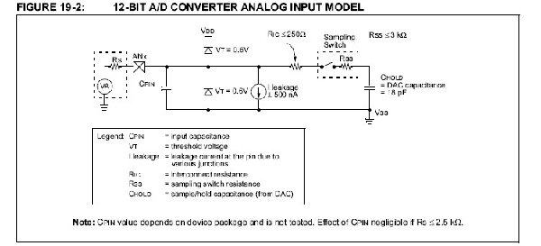
The dsPIC30F4013 already has protection diodes on the A/D inputs so there is no need to use any at all.  What is required is a series source resistor to protect these input diodes from getting damaged. What is required is a series source resistor to protect these input diodes from getting damaged. 
The A/D sampling switch resistance in the DSC is specified at 3K maximum. The interconnection resistance to the sampling switch is specified at 250 ohms maximum. If you use, for example, a source resistor of 1K between your analog source and the A/D input, this will equate to a charge time of the internal 18 pF holding capacitor of 383 nanoseconds when using the 5 time constant rule for charging capacitors to the source voltage. The 1K would be all you need with no diodes necessary as I mentioned. Just make sure that a minimum of 400 ns elapses between the time you change the channel address in the ADCON register and when you set the "GO" bit to start the conversion. If you do, you will be assured that no error (read - neglagable error) exists in your aquisition.
Hope this helps ....
Bill
Bill |
|
|
Back to top
|
|
|
blue hell
Site Admin
Joined: Apr 03, 2004
Posts: 24496
Location: The Netherlands, Enschede
Audio files: 298
G2 patch files: 320
|
| Posted: Fri Mar 28, 2008 12:37 pm Post subject:
|
|
|
| State Machine wrote: | | The dsPIC30F4013 already has protection diodes on the A/D inputs |
Wow pure luxury 
But ... should 5 times 383 ns not be more than 400 ns?
_________________
Jan
also .. could someone please turn down the thermostat a bit.
|
|
|
Back to top
|
|
|
bearblock

Joined: Sep 27, 2006
Posts: 90
Location: uk
Audio files: 1
|
|
|
Back to top
|
|
|
igor_d
Joined: Feb 17, 2008
Posts: 5
Location: Russia
|
| Posted: Fri Mar 28, 2008 1:54 pm Post subject:
|
|
|
| lowohm resistor + TVS (unipolar, 5V) - good solution. |
|
|
Back to top
|
|
|
State Machine
Janitor
Joined: Apr 17, 2006
Posts: 2810
Location: New York
Audio files: 24
|
|
|
Back to top
|
|
|
blue hell
Site Admin
Joined: Apr 03, 2004
Posts: 24496
Location: The Netherlands, Enschede
Audio files: 298
G2 patch files: 320
|
| Posted: Fri Mar 28, 2008 3:56 pm Post subject:
|
|
|
Thanks Bill, I read you wrong, sorry 
_________________
Jan
also .. could someone please turn down the thermostat a bit.
|
|
|
Back to top
|
|
|
State Machine
Janitor
Joined: Apr 17, 2006
Posts: 2810
Location: New York
Audio files: 24
|
| Posted: Fri Mar 28, 2008 3:57 pm Post subject:
|
|
|
| Quote: | | maybe overkill, but opamps are cheap. |
The "ideal diode" circuits are very good, no doubt about it there, but in this application really has no business sitting in front of the A/D of this chip True, op-amps are cheap, but ............ I think your gut feeling is correct, it's a bit overkill ...
Thanks for posting the circuit though .......
Bill |
|
|
Back to top
|
|
|
State Machine
Janitor
Joined: Apr 17, 2006
Posts: 2810
Location: New York
Audio files: 24
|
| Posted: Fri Mar 28, 2008 3:59 pm Post subject:
|
|
|
| Quote: | | Thanks Bill, I read you wrong, sorry Very Happy |
Oh Jan, you know me better .... No sorry necessary .... just a simple misread thats all ... I do it all the time .......
Bill |
|
|
Back to top
|
|
|
Tim Servo

Joined: Jul 16, 2006
Posts: 924
Location: Silicon Valley
Audio files: 11
|
| Posted: Thu May 29, 2008 6:58 pm Post subject:
Protecting A/D Pins on a Micro |
|
|
I agree with Blue Hell's answer (current limiting resistor - say 180 ohms, and a couple of schottky diodes - one from the signal line to +5V, the other from the signal line down to ground). However, I also found a nifty 'solution in a chip' from Littlefuse. It's the SP721 "TVS Diode Array." You get protection for six inputs in an 8-pin chip (available in DIP or SMT), and they go for about $1.40 each at Mouser. It sounds a little pricey until you consider that schottky diodes are going to be 7 cents each (if you buy 100, more if you don't buy that many), and the resistors cost about 2 cents each. Ring that up for six inputs and you've got (...runs out of fingers and toes... grabs calculator...) 96 cents. You've just spent almost as much money for a solution that takes up a lot more board space and 18 parts vs. 1. I know which way I'm going with my new digital stuff. 
Anyway, I thought is was kind of nifty.
Tim (can count up to twenty-one without a calculator) Servo |
|
|
Back to top
|
|
|
blue hell
Site Admin
Joined: Apr 03, 2004
Posts: 24496
Location: The Netherlands, Enschede
Audio files: 298
G2 patch files: 320
|
| Posted: Fri May 30, 2008 8:05 am Post subject:
Re: Protecting A/D Pins on a Micro |
|
|
| Tim Servo wrote: | | grabs calculator... |
 but you forgot about the placement costs (for us currently about 10 (us) cents I think ? for each part) and the tooling costs (depending on batch size), so that chippie is cheaper even. but you forgot about the placement costs (for us currently about 10 (us) cents I think ? for each part) and the tooling costs (depending on batch size), so that chippie is cheaper even.
I'm going to run down now to the hardware guy ... about half an hour ago I told him I was going to watch some soccer on the web while he was going to do some routing 
_________________
Jan
also .. could someone please turn down the thermostat a bit.
|
|
|
Back to top
|
|
|
Tim Servo
Joined: Jul 16, 2006
Posts: 924
Location: Silicon Valley
Audio files: 11
|
| Posted: Fri May 30, 2008 10:55 am Post subject:
Protecting A/D Pins on a Micro |
|
|
You're right. If you're having boards assembled by a board house, then fewer parts = lower cost. You'll also have fewer parts to keep in inventory. The chip solution works even better if you have something with lots of inputs (like an AVR with 23 I/O pins).
Tim (fewer parts = fewer things to forget) Servo |
|
|
Back to top
|
|
|
blue hell
Site Admin
Joined: Apr 03, 2004
Posts: 24496
Location: The Netherlands, Enschede
Audio files: 298
G2 patch files: 320
|
| Posted: Fri May 30, 2008 11:18 am Post subject:
|
|
|
Mr. hardware already knew, but erm .. he had something better anyway, I did what I could ... and I best keep to doing software I guess
_________________
Jan
also .. could someone please turn down the thermostat a bit.
|
|
|
Back to top
|
|
|
glitched
Joined: Mar 25, 2006
Posts: 80
Location: phila., pa USA
|
| Posted: Sun Jan 09, 2011 11:52 am Post subject:
|
|
|
I'm interested in using the SP721 for input protection, rather than Schottkey diodes/resistors, but I'm not sure how to apply it.
Let's say I have a PIC16F684, like the one in the VCLFO, mentioned above. I have 6 inputs on the PIC that I'd like to protect. The voltage range should be 0-5v.
From reading the data sheet and application notes, I would tie Vin- to the GND (0v) and Vin+ to +5v.
Would I need six of these chips to protect six inputs on the PIC or is there a certain type of configuration that I should know about?
EDIT: Reading more about TVS', would I simply use the inputs on the SP721 in parallel with the input lines to the PIC? That is, for instance:
| Code: | External voltage------->Pin 13 on PIC
|
|
IN(1) on SP721 |
Is that how it works?
Thanks for your help.
Regards,
-d |
|
|
Back to top
|
|
|
elmood
Joined: Sep 05, 2009
Posts: 22
Location: Toronto
|
| Posted: Sat Jan 22, 2011 10:58 am Post subject:
|
|
|
It's really important not to force too much current into the inputs on a PIC ADC. Even if the internal diodes can handle the current without being damaged, you will find that the accuracy of the ADC is adversely affected during over/under voltage, even on other inputs. This will cause weird behaviour if you're sampling from multiple inputs at the same time.
I think the best way is to not rely on the internal diodes at all... a series resistor and some schottky clamping diodes will probably work best. Of course a driving impedance as low as possible is good idea.. but be careful not to exceed the limit of the diodes.
Of course, an op amp is really only needed if you want an input impedance more than 5K or so, or want to do some low pass filtering. (also a good idea) |
|
|
Back to top
|
|
|
glitched
Joined: Mar 25, 2006
Posts: 80
Location: phila., pa USA
|
| Posted: Sat Jan 22, 2011 6:59 pm Post subject:
|
|
|
| I got some SP721 samples, so I'm going to use them on this LFO project. We'll see how the ADC reacts. Should be the economical solution I'm looking for. |
|
|
Back to top
|
|
|
glitched
Joined: Mar 25, 2006
Posts: 80
Location: phila., pa USA
|
| Posted: Tue Feb 22, 2011 9:03 pm Post subject:
|
|
|
I thought I'd update this post to say that the SP721app TVS worked well for my purposes. Well, sort of...
I didn't realize that the forward voltage drop was around 2V, typical! I was wondering why my external control voltages were barely doing anything to control my PIC-based LFO! |
|
|
Back to top
|
|
|
dshay
Joined: May 04, 2009
Posts: 18
Location: Minnesota
|
| Posted: Sat Aug 25, 2012 7:06 pm Post subject:
|
|
|
Two schottkys, one in series with signal, rectifier mode, one parallel (reverse protection), and a 5.1V Zener to clamp the signal is one method of how they keep severe transients from Piezos damaging an ADC. The resistor/capacitor are to lengthen the decay of the piezo signal, omit these.
A Zener is essentially a unipolar TVS diode, the people recommending TVSs, I agree with.
Circuit used from http://leucos.lstilde.org/wp/2009/06/piezo-transducer-signal-conditioning/
 |
|
|
Back to top
|
|
|
|

 Forum index » DIY Hardware and Software » Microcontrollers and Programmable Logic