| Author |
Message |
gddfp
Joined: Jan 11, 2009
Posts: 21
Location: Belgium
|
 Posted: Tue May 05, 2009 3:30 pm Post subject:
Inverter / Grounding Posted: Tue May 05, 2009 3:30 pm Post subject:
Inverter / Grounding |
  |
|
Hi all,
My first post here, please be mild.
I'm just starting out with some basic DIY, learning as much as I possibly can. Still have a long way to go with the most rudimentary of electronics principles, but I'm trying...
Right now I'm breadboarding a simple Inverter, based on a TL072. Real basic stuff: voltage in, inverted voltage out.
I kinda understand the schematic (included), but I think I'm having trouble with grounding. This is supposed to work, but all I get is the same (pos) voltage coming out.
I do not understand if and whereto I have to connect the 0V - to the input & output busses, only one of them, none... ?
This will be part of a separate desktop module, with its own separate PSU. It's not build in one of my modulars or anything.
Can someone please enlighten me how to measure and connect this properly ?
Thank you.
| Description: |
|

Download (listen) |
| Filename: |
inverter_schema.pdf |
| Filesize: |
9.4 KB |
| Downloaded: |
252 Time(s) |
|
|
|
Back to top
|
|
 |
JovianPyx

Joined: Nov 20, 2007
Posts: 1988
Location: West Red Spot, Jupiter
Audio files: 224
|
| Posted: Tue May 05, 2009 4:31 pm Post subject:
|
|
|
The ground symbol is the one connected to the smaller diagram lower left. This is the circuit point that should be connected to the input signal "ground". It is also connected to the OpAmp's "+" or non-inverting input. If you place an AC input into this circuit, the output should be inverted (or 180 phase change) with respect to the input and amplified by whatever gain is designed into the the OpAmp circuit. In this case, the gain is -1 because the two resistors (input and feedback) are the same and the minus sign is because it's an inverter.
This is a DC amplifier. You can test it using a DC voltage, like a simple dry cell - which when new produces 1.5 volts. Connect the negative side to ground, the positive side to the inverter's input. The output should read on a DVM as -1.5 volts. If you flip the dry cell around so that + is to ground and the - terminal goes to the inverter input, then the output should be +1.5 volts.
The 0 (zero) volt connection is the ground connection which should go to the opamp + input and to the input signal ground as well as the output signal ground.
In fact, many inverter circuits use a simple wire in place of the 47 K resistor... I believe that's there to make the circuit "more accurate" as an "operational amplifier" - operational as in the arithmetic operation of summation.
_________________
FPGA, dsPIC and Fatman Synth Stuff
Time flies like a banana.
Fruit flies when you're having fun.
BTW, Do these genes make my ass look fat?
corruptio optimi pessima
|
|
|
Back to top
|
|
|
gddfp
Joined: Jan 11, 2009
Posts: 21
Location: Belgium
|
|
|
Back to top
|
|
|
JovianPyx
Joined: Nov 20, 2007
Posts: 1988
Location: West Red Spot, Jupiter
Audio files: 224
|
| Posted: Tue May 05, 2009 6:16 pm Post subject:
|
|
|
If things are in fact hooked as you show in the second schematic (which is correct) then the output should be either +9V or -9V depending on the polarity of the battery connection to the plug. It should NOT be 15.
Are you quite sure that both the feedback and input resistors are 100K? If the feedback resistor is larger than the input resistor, you could get positive gain. Or if the input resistor is smaller, the same thing would happen. Let's say that the input resistor is 10K and the feedback is 100K, you'd get a gain of 10 - in this case, the circuit would try to multiply the input voltagbe by the gain of 10, but because the power supply is only 15 volts, it can't produce an output of 90V, so it goes as high as it can or 15 volts.
Make sure the resistor values are really as they are stated in the schematic...
I'm curious, if you reverse the polarity of the battery, does the polarity of the output also reverse? (it should)...
_________________
FPGA, dsPIC and Fatman Synth Stuff
Time flies like a banana.
Fruit flies when you're having fun.
BTW, Do these genes make my ass look fat?
corruptio optimi pessima
|
|
|
Back to top
|
|
|
gddfp
Joined: Jan 11, 2009
Posts: 21
Location: Belgium
|
Posted: Wed May 06, 2009 2:19 am Post subject:

Subject description: (solved) |
|
|
Hi Scott,
I have solved the problem.
Turned out I made a mistake on the breadboard (this is my first foray in breadboarding as well). The 100k input resistor was connected over the same board column... (so: input <--> 100k <--> pin 2 all on the same column  ) Rather stupid of me - sorry ! ) Rather stupid of me - sorry !
Anyway, it works now, and I want to thank you for your help and explanations. They certainly cleared up most things, plus I learned some more about OpAmps along the way.
Guy |
|
|
Back to top
|
|
|
JovianPyx
Joined: Nov 20, 2007
Posts: 1988
Location: West Red Spot, Jupiter
Audio files: 224
|
| Posted: Wed May 06, 2009 6:10 am Post subject:
|
|
|
Don't apologize - making mistakes is what breadboards are for! You also now have some practical experience in some troubleshooting and will know what to expect and some things to try in the future. Glad to hear it's working and that you're gaining knowledge. Welcome to "our" little world. 
_________________
FPGA, dsPIC and Fatman Synth Stuff
Time flies like a banana.
Fruit flies when you're having fun.
BTW, Do these genes make my ass look fat?
corruptio optimi pessima
|
|
|
Back to top
|
|
|
gddfp
Joined: Jan 11, 2009
Posts: 21
Location: Belgium
|
| Posted: Wed May 06, 2009 6:38 am Post subject:
|
|
|
Thanks !
Onwards to an inverter with attenuator now...  |
|
|
Back to top
|
|
|
Tony Deff
Joined: May 25, 2008
Posts: 51
Location: Suffolk, UK
|
Posted: Wed May 06, 2009 11:13 am Post subject:
Op-amp bias
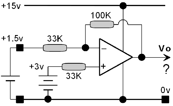
Subject description: When pin 3 doesn't necessarily connect to Ground |
|
|
If you are confident you know the output voltage of the following arrangement (  cough cough, assuming it is wired-up correctly!), then there is no point in downloading the following PDF attachment. cough cough, assuming it is wired-up correctly!), then there is no point in downloading the following PDF attachment.
| Description: |
| This is actually a filter — it filters-out those who know their op-amps!! |
|
| Filesize: |
10.66 KB |
| Viewed: |
243 Time(s) |
| This image has been reduced to fit the page. Click on it to enlarge. |
|
| Description: |
| Universal formula for op-amp output, which can include a DC bias at the + input. |
|
Download (listen) |
| Filename: |
Universal Op-Amp Bias.pdf |
| Filesize: |
137.23 KB |
| Downloaded: |
220 Time(s) |
|
|
|
Back to top
|
|
|
JovianPyx
Joined: Nov 20, 2007
Posts: 1988
Location: West Red Spot, Jupiter
Audio files: 224
|
| Posted: Wed May 06, 2009 12:46 pm Post subject:
|
|
|
That looks like a homework question for an electronics class...
_________________
FPGA, dsPIC and Fatman Synth Stuff
Time flies like a banana.
Fruit flies when you're having fun.
BTW, Do these genes make my ass look fat?
corruptio optimi pessima
|
|
|
Back to top
|
|
|
gddfp
Joined: Jan 11, 2009
Posts: 21
Location: Belgium
|
Posted: Wed May 06, 2009 2:26 pm Post subject:
Re: Op-amp bias
Subject description: When pin 3 doesn't necessarily connect to Ground |
|
|
| Tone-Deaf wrote: | | If you are confident you know the output voltage of the following arrangement ( cough cough, assuming it is wired-up correctly!), then there is no point in downloading the following PDF attachment. |
Pretty clear to me: 42 !
(I've always felt that there was something fundamentally wrong with the Universe)
|
|
|
Back to top
|
|
|
|

 Forum index » DIY Hardware and Software » Developers' Corner
