| Author |
Message |
DGTom

Joined: Dec 08, 2008
Posts: 211
Location: Adelaide
Audio files: 3
G2 patch files: 1
|
 Posted: Tue Dec 01, 2009 6:47 pm Post subject: Posted: Tue Dec 01, 2009 6:47 pm Post subject:
|
  |
|
tbh screw terminals are a little... clumsy, ok if you are leaving the electronics exposed or space is not a concern. .100 headers are a much better way of doing it IMO. I build all my proto. cct.s with rows of them on each side & have a bunch of Pots, Switches, LEDs etc. that just plug in for testing.
With bbobs board, if I wanted to keep hook-up flexiable I'd use the proto area as a bank of headers & link stuff into it with wires.
having the pads for power starve is great  |
|
|
Back to top
|
|
 |
Inventor
Stream Operator

Joined: Oct 13, 2007
Posts: 6221
Location: near Austin, Tx, USA
Audio files: 267
|
| Posted: Tue Dec 01, 2009 8:06 pm Post subject:
|
|
|
| DGTom wrote: | tbh screw terminals are a little... clumsy, ok if you are leaving the electronics exposed or space is not a concern. .100 headers are a much better way of doing it IMO. I build all my proto. cct.s with rows of them on each side & have a bunch of Pots, Switches, LEDs etc. that just plug in for testing.
With bbobs board, if I wanted to keep hook-up flexiable I'd use the proto area as a bank of headers & link stuff into it with wires.
having the pads for power starve is great |
DGTom, are we talking about the same thing? These screw terminals are on .100 centers just like headers and they do not leave the electronics exposed. Perhaps you are thinking of a different type of screw terminal. The type I am thinking of will do nicely in place of headers. Though the disadvantage is price, about 30 cents per terminal. Should I look up a datasheet for them or a photo?
Les
_________________
"Let's make noise for peace." - Kijjaz |
|
|
Back to top
|
|
|
Inventor
Stream Operator
Joined: Oct 13, 2007
Posts: 6221
Location: near Austin, Tx, USA
Audio files: 267
|
|
|
Back to top
|
|
|
Inventor
Stream Operator
Joined: Oct 13, 2007
Posts: 6221
Location: near Austin, Tx, USA
Audio files: 267
|
| Posted: Tue Dec 01, 2009 8:18 pm Post subject:
|
|
|
Oh yes, and one more thing - you can have your cake and eat it too! By that I mean that a row of holes for screw terminals will also accept .100 headers and will also accept wires. You just have to make the holes the proper size to accept the screw terminals and you're good to go. So it's not an either-or choice but a both-and choice, which is a winner for everyone...
Les
_________________
"Let's make noise for peace." - Kijjaz |
|
|
Back to top
|
|
|
DGTom
Joined: Dec 08, 2008
Posts: 211
Location: Adelaide
Audio files: 3
G2 patch files: 1
|
| Posted: Tue Dec 01, 2009 8:44 pm Post subject:
|
|
|
oh I think they are really cool.
By "electronics exposed" I meant that the screw terminals seem better suited (to me) for devices like your sculptures which aren't inside an enclosure of some sort.
These:

& these;

are what I mean. Super-cheap & make assembly so, so easy.
You actually just touched on something that the screw terminals really have over these; multiple connections! Ideal in a lunetta world!! |
|
|
Back to top
|
|
|
Inventor
Stream Operator
Joined: Oct 13, 2007
Posts: 6221
Location: near Austin, Tx, USA
Audio files: 267
|
| Posted: Wed Dec 02, 2009 12:28 pm Post subject:
|
|
|
I see both sides of the coin. On the one hand, Mathe is correct that you can do anything you want with those little eChucK breakout boards. And it is also true that many of us would like a nice Lunetta board for gifts or sharing with others.
Certainly if you're a Lunetta head you'll appreciate both approaches for different reasons. I'm inclined to make a LunettaBoard myself if someone would suggest a suitable design.
Also I'm wondering for the future about the next batch of eChucK breakout boards. They should have a smaller hole size and maybe another row or two I think. What are your suggestions?
Les
_________________
"Let's make noise for peace." - Kijjaz |
|
|
Back to top
|
|
|
electri-fire
Joined: Jul 26, 2006
Posts: 536
Location: Dordrecht NL
Audio files: 4
G2 patch files: 4
|
| Posted: Wed Dec 02, 2009 12:52 pm Post subject:
|
|
|
| Inventor wrote: | | I'm wondering for the future about the next batch of eChucK breakout boards. They should have a smaller hole size and maybe another row or two I think. What are your suggestions? |
Bigger for not significant higher price would be nice, but...
They suit me fine the way they are. I have enough room for ground busses for pulldowns and timing capacitors. The holes are big enough to accommodate headers, but not too big for regular components, the solder fills them up nicely. I will mostly use them in a casing, but circuitboard mounted pots can be inserted as is. That wouldn't be the case with smaller holes.
When going bigger you would need place for two 16pin CMOS, with an extra ground buss in between. That would mean double size, else you just waist room most of the time. Even then, keeping in mind the modular philosophy, I might still want the present format.
edit: my pots span 5 holes,next pot would need 2 holes in between, I have ground busses at both sides, so 6 extra colloms would fit two of my pots, making a total of 16 colloms, add two extra ground busses in between (you need more for two CMOS) , this would lead to 18 colloms.
The colloms are 5 holes high now, one hole on both sides of the two center busses are taken by the IC, leaving 4 holes for pulldowns/timing caps. Enough I think. It's easier to make a solderbridge than do a trace cut. So, when adding extra height you could add a collom of two connected holes above the present 5 hole colloms. To accommodate pots and such. Doing this on both sides of the board would lead to a 16x18 hole "double" board.
That said, I might still want the present format.
Still I might want the present format.
I might want the present format still.
Want I still the present might format?
What do you think?
.
Last edited by electri-fire on Wed Dec 02, 2009 1:28 pm; edited 1 time in total |
|
|
Back to top
|
|
|
Inventor
Stream Operator
Joined: Oct 13, 2007
Posts: 6221
Location: near Austin, Tx, USA
Audio files: 267
|
|
|
Back to top
|
|
|
electri-fire
Joined: Jul 26, 2006
Posts: 536
Location: Dordrecht NL
Audio files: 4
G2 patch files: 4
|
| Posted: Wed Dec 02, 2009 1:48 pm Post subject:
|
|
|
| Inventor wrote: | | The reason I say that I'd like to make the boards a bit bigger is because this design doesn't really work for a 16 pin IC. We need one more row to do it right. That is, unless someone can come up with a more compact layout. |
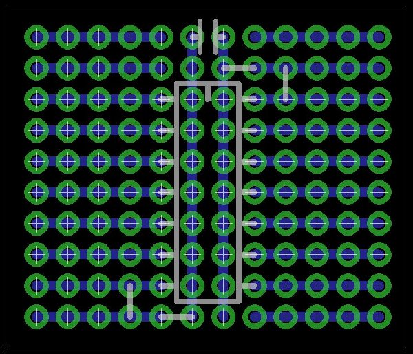
Ah, you have the center busses assigned to + an ground. I have both to ground. The board suits 16pin CMOS just fine.
The + buss is seldom used, if so, for manual clock, inhibit/engage, reset, or other "shoot a high into some point" function. You need more ground busses, not so much + bus.
Here's my setup: Red= + bus, White (and Green jumpers) are ground, Blue are header connector for battery, also Green is bypass capacitor.
.
| Description: |
|
| Filesize: |
56.43 KB |
| Viewed: |
8070 Time(s) |

|
|
|
|
Back to top
|
|
|
|

 Forum index » DIY Hardware and Software » Lunettas - circuits inspired by Stanley Lunetta