| Author |
Message |
metal_head_82

Joined: Dec 27, 2009
Posts: 34
Location: Germany
Audio files: 2
|
|
|
Back to top
|
|
 |
synthmonger
Joined: Nov 16, 2006
Posts: 578
Location: flada
Audio files: 3
|
|
|
Back to top
|
|
|
metal_head_82
Joined: Dec 27, 2009
Posts: 34
Location: Germany
Audio files: 2
|
 Posted: Mon Nov 29, 2010 4:25 am Post subject: Posted: Mon Nov 29, 2010 4:25 am Post subject:
|
  |
|
Hey Snthmonger,
I lowered to summing resistors on purpose.
They were 100k but that didn't gave me the filter sweeps I wanted - so I lowered them down. The circuit itself has also changed. But it's not finished yet. I'm still trying to improve the frequency range.
The filters you posted look pretty cool. I think I'll have to breadboard them.
My Idea for this filter came from some simple, passive VCF circuits which didn't offer Resonance control. So I tried to include the technique used there in an active design.
I was pretty sure that I came up with something new 
But as I already mentioned: I'm sure that someone else had the same Idea.
Had the same issue with a 2 op amp LFO I thought I designed.
But I realized that it was such a simple standard design - it has been posted several times in many forums. So no post here.
I'm currently building a little filter toy with my design. Perhaps the filters you posted work out better. I will give it a try.
Thx for the hint! 
_________________
"I don't care much about music. What I like is sounds." |
|
|
Back to top
|
|
|
umschmitt

Joined: Jun 29, 2011
Posts: 189
Location: brrlin
Audio files: 11
|
| Posted: Thu Dec 22, 2011 6:21 am Post subject:
|
|
|
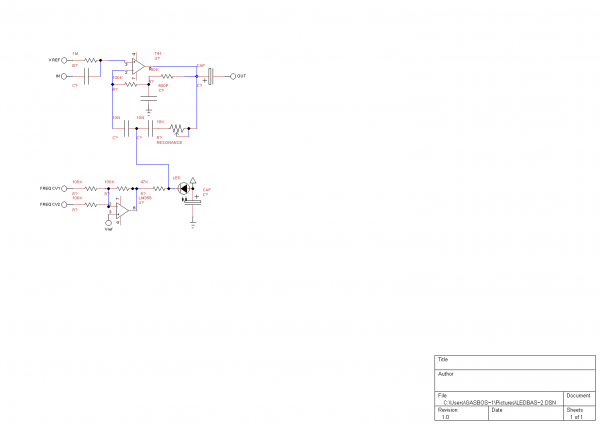
Hej metal_head_82. I know this is an old topic, but by chance did you succeed in improving the frequency range of you filter ? I'm using it - roughly adapted to 5 volts ! - in this modded circuit
http://electro-music.com/forum/phpbb-files/mutant_ds_7_prelim_schem_525.png
and it sounds good, but I'd like to be able to make it growl… So which parameters should be changed ? Do you have an idea of the equations involved here ? (is it even possible ?)
Thanks in advance !
_________________
::U::N::S::C::H::N::E::L::L:: |
|
|
Back to top
|
|
|
metal_head_82
Joined: Dec 27, 2009
Posts: 34
Location: Germany
Audio files: 2
|
| Posted: Mon Jan 02, 2012 9:23 am Post subject:
|
|
|
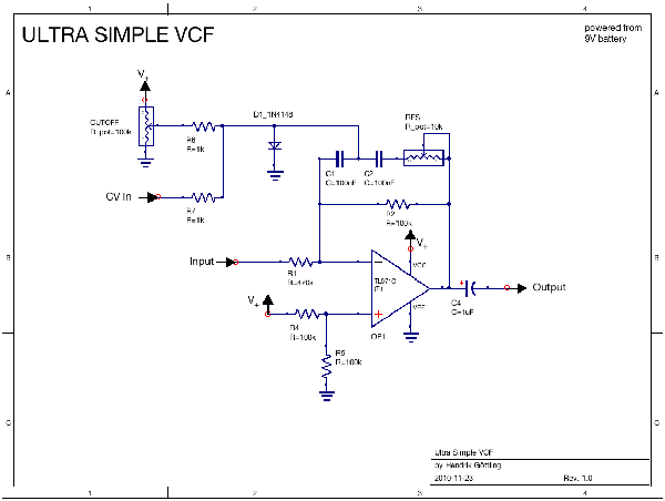
This is an active bridged-T filter.
Just google for bridged-T filter and you should find the equations. I selected the values by trial and error 
To improve the frequency range you could exchange the diode with a garden variety transistor. e.g. BC547.
Connect the emitter to the junction of the two caps and the collector to ground (0V). Apply the CV to base. This should improve the behaviour to cv and give you some more control - especially with low CVs. You should then rise the summing resistor values to at least 100k. To limit the filter's frequency response when no CV is applied you could try to place a resistor in parralel to collector and emitter.
I think this is the same way Ray Wilson achieved a VCF in one of his designs. I'm pretty sure I saw this method in one of his old devices. I came up with this when I modified my WSG. Now it has some nice "quasi-vcf"
Hope this helps a little.
Greetz
_________________
"I don't care much about music. What I like is sounds." |
|
|
Back to top
|
|
|
umschmitt
Joined: Jun 29, 2011
Posts: 189
Location: brrlin
Audio files: 11
|
| Posted: Mon Jan 02, 2012 5:56 pm Post subject:
|
|
|
Thanks. I ended up doing the same, using a transistor, on the advice from people here, and it works great ! I tried using 100k resistors for the CVs, without much success I'm afraid. I had very little range on the controls. So back to 10k. Putting a resistor across the transistor is great too, actually it answers an issue I had concerning the pots' travel…
So. Besides, I had put this transistor the other way round, like I thought it should have to be (as I mentioned on your VCO topic). The fact is that both work. I won't even ask questions here. I just don't understand.
By the way, your filter is among others discussed here.
_________________
::U::N::S::C::H::N::E::L::L:: |
|
|
Back to top
|
|
|
mrkva

Joined: Jan 25, 2012
Posts: 41
Location: poland/slovakia/netherlands
|
| Posted: Tue Feb 07, 2012 2:19 pm Post subject:
|
|
|
| Any news with this one? Any upgrades of the schematic / values? I really like the simplicity! |
|
|
Back to top
|
|
|
tokyomatik

Joined: Jan 20, 2011
Posts: 171
Location: berlin
Audio files: 6
|
| Posted: Thu Mar 01, 2012 9:53 pm Post subject:
|
|
|
i tried to improve the sweep and cv following the tips here on this thread, but didn't worked...i would be also curious to see new schematics
i'm trying to use this filter to build a baby 8 for a friend, with internal vco and vcf controlled by the sequencer
kind of self contained groovebox
pretty funny till now, but sure could be even better
when i feed the signal to the filter the volume goes drastically down
and even with the cutoff completely open, i don't have the original sfrequency spectrum of the original, i loose part of the bottom and start to sound almost like an hipass
plus the pots don't have a linear response, too less and then too much if u know what i mean, should i try with a couple of logs ?
anyway the sound is already more interesting than the wsg filter for example, at least the resonance is not only perceived
keep up the good work
peace |
|
|
Back to top
|
|
|
MrSparkle
Joined: Mar 11, 2012
Posts: 1
Location: Portland, OR
|
| Posted: Sun Mar 11, 2012 5:42 am Post subject:
|
|
|
| tokyomatik wrote: |
when i feed the signal to the filter the volume goes drastically down
|
Replace R1 with a 100k resistor. This should fix the volume drop problem without (drastically) affecting the operation of the filter. You could even go lower to compensate a bit more if needed. Note that this will lower the input impedance of the filter, so make sure the output of the previous stage has a low enough output impedance, or you could get attenuation from the impedance mismatch (this shouldn't generally be a problem unless you have a volume pot before the filter or something like that)
I'm not sure why R1 is 470k in the first place. It looks like maybe a mistake? Or maybe the attenuation was intentional? Sorry I'm new here.
Cheers. |
|
|
Back to top
|
|
|
ELEKTRICGASCHIEF
Joined: Jul 17, 2012
Posts: 2
Location: SCOTLAND
|
|
|
Back to top
|
|
|
JingleJoe

Joined: Nov 10, 2011
Posts: 878
Location: Lancashire, England
Audio files: 14
|
| Posted: Tue Jul 17, 2012 1:41 pm Post subject:
|
|
|
The polarized capacitor you have on your LED might be to blame, if you get oscillation you may need to adjust the resonance control or input amplitude.
_________________
As a mad scientist I am ruled by the dictum of science: "I could be wrong about this but lets find out"
Green Dungeon Alchemist Laboratories |
|
|
Back to top
|
|
|
Rolbista
Joined: Nov 17, 2012
Posts: 23
Location: Poland
|
Posted: Sat Nov 17, 2012 7:26 am Post subject:
VCF noise?
Subject description: noisy output |
|
|
| Hey all, first post here, slapped this VCF together and works quite nice, but i have a problem with hiss and noise with cutoff and resonance set low (as in, cutoff completely open, and minimal resonance). At frst I thought it was ceramic caps for those two 100nF, but swapped them for film ones and the noise is only a littke better. I used 10k resistors for CV, and 100k for input, there is also a BC546 instead of the diode. Should I trim the input signal more? Or maybe it has to be like this? I used the schematic at the top of this thread. |
|
|
Back to top
|
|
|
JingleJoe
Joined: Nov 10, 2011
Posts: 878
Location: Lancashire, England
Audio files: 14
|
| Posted: Thu Nov 29, 2012 3:41 am Post subject:
|
|
|
What op amp are you using? people usually blame op amps but maybe you need some high pass filtering at the input/output?
Also your connections between the circuit and amplifier, or whatever you are listening to it with, could be sheilded poorly, you could even be in an electromagnetic field hot spot 
_________________
As a mad scientist I am ruled by the dictum of science: "I could be wrong about this but lets find out"
Green Dungeon Alchemist Laboratories |
|
|
Back to top
|
|
|
Rolbista
Joined: Nov 17, 2012
Posts: 23
Location: Poland
|
| Posted: Thu Nov 29, 2012 2:11 pm Post subject:
|
|
|
| op amp - TL071cn , i used normal guitar cables and a small guitar amp. In the meantime I tried it during a band practice, and we are so loud we barely hear that noise. It would be nice however, to have it clean for studio purposes. Also, what voltage swing from an LFO should I use to modulate it from full to no cutoff, 0-9V? |
|
|
Back to top
|
|
|
JingleJoe
Joined: Nov 10, 2011
Posts: 878
Location: Lancashire, England
Audio files: 14
|
| Posted: Fri Nov 30, 2012 1:07 pm Post subject:
|
|
|
There is another thread about simple VCFs somewhere else on this forum but I don't know what it was called anymore (I think umschmitt posted there too), anyway a very similar circuit was used but with a transistor in place of the diode, this should help with noise problems and allow you to tailor the control voltage range.
_________________
As a mad scientist I am ruled by the dictum of science: "I could be wrong about this but lets find out"
Green Dungeon Alchemist Laboratories |
|
|
Back to top
|
|
|
max92
Joined: Aug 04, 2010
Posts: 17
Location: Sweden
|
| Posted: Sun Dec 16, 2012 6:13 pm Post subject:
|
|
|
I've just built this circuit using the original circuit at the top, only exception being that I use a tl072 instead of the tl071, but I guess that shouldn't matter.
My plan was to use this as a pedal for a bass guitar.
I've got two problems though:
1. There's a lot of noise when the filter is "open".
2. When the filter is "closed" it still let pretty much through. I would guess it is between 2-5 khz
So the noise. My first guess is that is because of the weak signal coming from the bass guitar. Could this be fixed with any coupling capacitors or change of current?
The cutoff frequency I guess should be a matter of changing a resistor somewhere or? |
|
|
Back to top
|
|
|
elmegil

Joined: Mar 20, 2012
Posts: 2179
Location: Chicago
Audio files: 16
|
| Posted: Sun Dec 16, 2012 11:06 pm Post subject:
|
|
|
| pre-amp stage? |
|
|
Back to top
|
|
|
wahoah
Joined: Jan 27, 2013
Posts: 6
Location: USA
|
| Posted: Sun Jan 27, 2013 2:52 pm Post subject:
|
|
|
I have the same problem with the "white noise" that my VCF produce
HELP! |
|
|
Back to top
|
|
|
bubzy

Joined: Oct 27, 2010
Posts: 594
Location: United Kingdom
Audio files: 64
|
| Posted: Mon Jan 28, 2013 6:22 am Post subject:
|
|
|
| max92 wrote: | I've just built this circuit using the original circuit at the top, only exception being that I use a tl072 instead of the tl071, but I guess that shouldn't matter.
|
nope.
| Quote: |
My first guess is that is because of the weak signal coming from the bass guitar. |
yup.
as elmigil has pointed out, this circuit would require a preamp from anything that has a low output such as a bass guitar. you might want to look up a simple high gain op amp circuit, you could even use the other half of the tl072.
| Quote: |
I have the same problem with the "white noise" that my VCF produce
HELP!
|
firstly  to electro-music to electro-music
and we will need a little more information, what signal are you putting into this, how is it powered? have you altered any of the component values?
information is power
_________________
_Richard_ |
|
|
Back to top
|
|
|
analog_backlash

Joined: Sep 04, 2012
Posts: 393
Location: Aldershot, UK
Audio files: 21
|
| Posted: Mon Jan 28, 2013 4:24 pm Post subject:
|
|
|
Hi everyone involved.
This may be a really idiotic comment, but I can't seem to find any mention of screened connections to the input and output jacks, which I would do as a matter of course. As I say, this may be stating the "bleedin' obvious" but it depends on how new you are to electronics. I certainly would not have thought of it when I first started out.
Just an observation 
Gary |
|
|
Back to top
|
|
|
wahoah
Joined: Jan 27, 2013
Posts: 6
Location: USA
|
| Posted: Tue Jan 29, 2013 8:08 pm Post subject:
|
|
|
| Quote: |
firstly to electro-music
and we will need a little more information, what signal are you putting into this, how is it powered? have you altered any of the component values?
information is power |
Hi! my VCF is powered by 9v comming from a wall wart adapter, my incomming signal is a Atari Punk Console powered by a 9v battery.
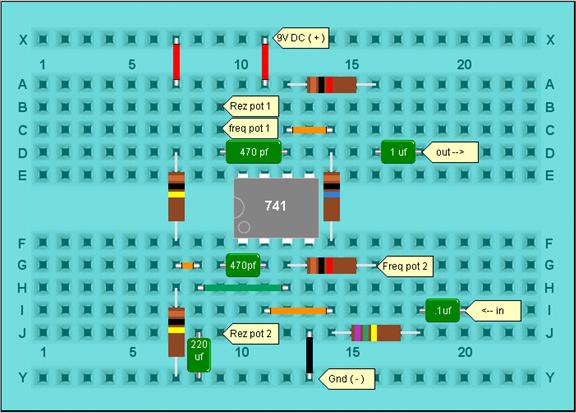
Ive made a few changes, first i changed the diode 1n4148 with a yellow led and replaced the 470kohms resistor on the input signal with a 100kohms
 |
|
|
Back to top
|
|
|
2kohm

Joined: Feb 19, 2013
Posts: 52
Location: germany
Audio files: 4
|
| Posted: Sun Mar 24, 2013 11:22 pm Post subject:
|
|
|
mh... i use a 470K input resistor ( tested with iphone audio input ) and with my lm324 osc. smaler value bring me dist and noise
sounds nice an clean, but i think the filter add´s a lot of ultra high frequencies.
i used resistors in series with the pots to get a nice scale.
anybody else tried this filter or have some modifications ?
i like the sound off this filter!!!
_________________
Shop
Videos
Stromakustik.de |
|
|
Back to top
|
|
|
bubzy
Joined: Oct 27, 2010
Posts: 594
Location: United Kingdom
Audio files: 64
|
| Posted: Mon Mar 25, 2013 5:42 am Post subject:
|
|
|
| wahoah wrote: | | Hi! my VCF is powered by 9v comming from a wall wart adapter, my incomming signal is a Atari Punk Console powered by a 9v battery. |
whoah, I totally lost this thread. the noise is likely as analog_backlash said, a grounding issue, you have 2 separate power supplies there, if you do this you should "common" the grounds, so just run a bit of wire from the 0v of the battery to the 0v of the wall-wart
_________________
_Richard_ |
|
|
Back to top
|
|
|
2kohm
Joined: Feb 19, 2013
Posts: 52
Location: germany
Audio files: 4
|
|
|
Back to top
|
|
|
baudrate

Joined: Mar 19, 2012
Posts: 27
Location: Utah
|
| Posted: Mon Mar 25, 2013 10:12 am Post subject:
|
|
|
| 2kohm wrote: |
i used resistors in series with the pots to get a nice scale.
|
I plan on adding some trimmers. I can't wait to get home tonight to throw this together on the breadboard. |
|
|
Back to top
|
|
|
|

 Forum index » DIY Hardware and Software » Developers' Corner