RingMad

Joined: Jan 15, 2011
Posts: 428
Location: Montreal, Canada
Audio files: 4
|
 Posted: Thu Sep 03, 2015 2:46 pm Post subject:
"Bull's Eye" Wall Game Lightbox Posted: Thu Sep 03, 2015 2:46 pm Post subject:
"Bull's Eye" Wall Game Lightbox
Subject description: with electronical illumination animation |
  |
|
Midway "Bull's Eye" Lightbox.
DEMO VIDEO : vimeo.com/136931561.
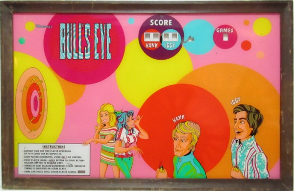
This is an animated lightbox I made from the painted plexiglas panel and frame from a "Bull's Eye" wall game made by Midway circa 1972. Before videogames, people used to play these. It was a 2-player dart game with hand controls to select when to release the dart, and it would take one of 3 trajectories and hit one of several spots on the dartboard. All I had was this piece, not the whole machine. I've only seen a photo of the original interior with a bunch of light bulbs and the electro-mechanical control mechanism. If you want to see the real machine working, someone posted this video on youtube.
I simplified the action and just have one player throwing, and the dart follows only one trajectory. The bull's eye is either hit or missed.
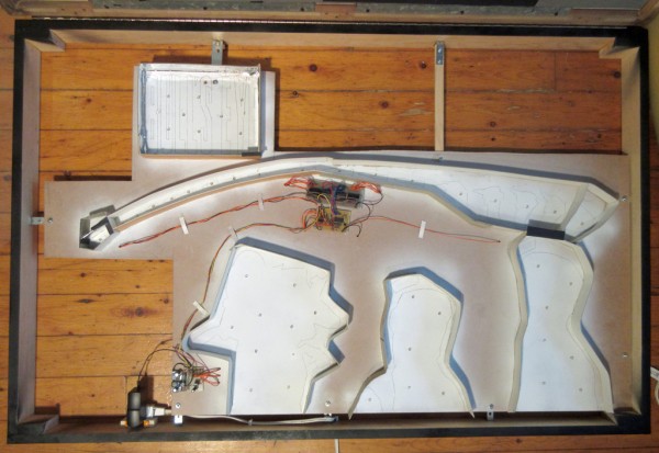
I built an open box frame to hold the light-panel, electronics and cardboard light isolators, and it's attached to the artwork frame using a piano hinge and a couple of magnetic latches.
* 49 warm white "straw hat" LEDs running on 12V regulated "wall wart" power supply. 22 of them are always on, for general illumination, 8 are for the Bull's Eye title letters, which are usually on but also flash when the bull's eye target is hit. The rest are for the hand and dart chasers, and the 2 possible dartboard hits.
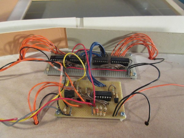
* The 2 chasers for the hand and dart trajectory use 74HC595 shift registers and TD62783 transistor array drivers.
* A PICAXE-14M2 microcontroller is used for the logic sequence, clocking the shift registers, controlling the display of the other LEDs.
* A pre-made LM2596 buck converter board is used to drop the voltage down to 7.5V which is then fed to an LM7805 voltage regulator to supply the PICAXE and 74HC595's. I probably could have skipped the regulator and had the buck converter supply the 5V, but I felt it was safer somehow.
* Some of the logic involves randomness: the length of time between dart throws and if the bull's eye target is hit or missed.
I can't believe I didn't use any CMOS!
.: James :.
.: www.jamesschidlowsky.ca :.
| Description: |
| Here's a close-up of the main circuit boards. The wires to the LEDs go through holes to the other side. |
|
| Filesize: |
289.55 KB |
| Viewed: |
410 Time(s) |
| This image has been reduced to fit the page. Click on it to enlarge. |
|
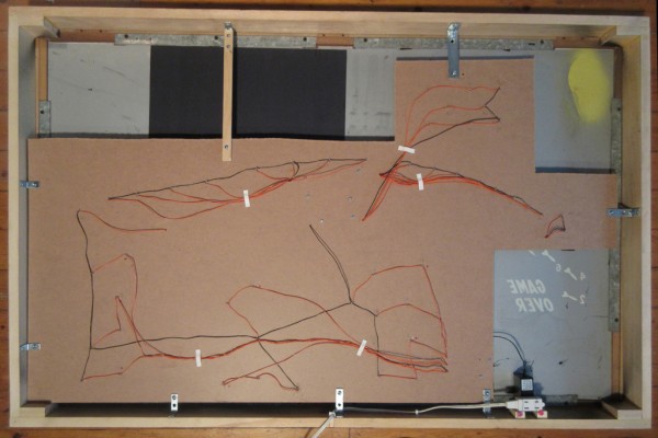
| Description: |
| The back of the light/circuit board panel, with the wiring to the LEDs. |
|
| Filesize: |
364.46 KB |
| Viewed: |
405 Time(s) |
| This image has been reduced to fit the page. Click on it to enlarge. |
|
| Description: |
|
| Filesize: |
637.41 KB |
| Viewed: |
403 Time(s) |
| This image has been reduced to fit the page. Click on it to enlarge. |
|
| Description: |
| The original frame and artwork (approximate dimensions: 130 x 83 cm or 51 x 32 inches). |
|
| Filesize: |
151.83 KB |
| Viewed: |
409 Time(s) |
| This image has been reduced to fit the page. Click on it to enlarge. |
|
|
|

 Forum index » Discussion » Schmooze » Miscellaneous DIY Art

