| Author |
Message |
ianbax
Joined: Apr 20, 2022
Posts: 42
Location: Sheffield, UK
|
 Posted: Sun Apr 23, 2023 1:56 pm Post subject:
Lunetta Touch Switches Posted: Sun Apr 23, 2023 1:56 pm Post subject:
Lunetta Touch Switches
Subject description: Adding touch switches to lunetta |
  |
|
Hi all - I've got an idea for a module for my lunetta and have researched some circuits but wanted to - once again! - seek the electronics wisdom on this board.
So I have a 4051 based sequencer. I hope I don't have to go too much in depth about that. The A, B and C inputs which select potentiometers 1-8 are brought out to the front panel. For conventional sequencing a binary counter (e.g. 4040) can be patched to A, B and C and the the 'resistance out' patched to an oscillator (across its pitch potentiometer) so you get 8 pitches repeated in a loop. A refined version of this https://hackaday.com/2015/02/23/logic-noise-the-switching-sequencer/ (just one example of this well documented circuit).
Of course any high/low combination can be patched to A, B and C so there's the possibility to add random gates, up/down counters, etc.
My mind went to having 8 switches, which could be coded to binary using a priority encoder making a sort of primitive keyboard, that would play the 8 pitches determined on the sequencer panel. Of course I could just solder up some momentary switches, those big arcade style buttons say but I've always been into the Buchla touch keyboard. I thought I may be able to do a lunetta version of that. I like the idea of single touch pads, rather than gaps bridged by the finger so I found this circuit (attached image): http://www.learningaboutelectronics.com/Articles/Touch-sensor-circuit-with-NAND-gate.php
Which claims to generate a touch sensitive switch from a 4011 NAND gate.
It works when you wire it up and sure the LED lights up on touch but on probing what's actually going on at the output it's actually a fast moving square wave (obvious when you patch it to a gate in or clock in). So what's going on here? The explanation on the page...
When we touch the touch wire, we are essentially acting as a resistor, creating a voltage divider circuit. Our body resistance can range anywhere from 100KΩ when dry to anywhere to about 1KΩ when wet. Either way, our body's resistance is much lower than the 10MΩ resistor. So it only a small amount of the 5V falls across our body. Doing the math, the voltage that falls across our body would be V= (5V)(100KΩ)/(100KΩ +10MΩ)≈ 0.05V, which is essentially 0 volts. The NAND gate reads this as a logic 0. (0.05V is way under half of the power supply voltage, which is 5V). So the logic level now at the inputs of the NAND gate changes to LOW (or 0). According to NAND gate logic, 2 LOWs at the input produce a HIGH logic level at the output, so the LED now powers on.
...doesn't seem right to me. Is it that you're finger touching the gate input is just creating interference? Just static confusing the input? I tried essentially the same circuit with a 40106 and got a similar result.
Anyway, I'm been wondering if this could be exploited - rectifying the square wave to a consistent high signal? Is that possible? Or connecting it to a re-triggerable monostable to get a high signal until the finger is released - I simulated this in falstad and it worked but I haven't got a monostable chip (e.g. 4098) to try it for real.
Or is all that just pointless - I should just mix in a proper capacitive touch circuit with an arduino. I've been looking at the adafruit breakout which gives 12 switches on one board, or there's heaps of pre-made ones on ebay for pennies. I know that isn't strictly lunetta so I won't ask anything more about that circuit here.
| Description: |
|
| Filesize: |
26.62 KB |
| Viewed: |
102 Time(s) |
| This image has been reduced to fit the page. Click on it to enlarge. |

|
|
|
|
Back to top
|
|
 |
PHOBoS

Joined: Jan 14, 2010
Posts: 5792
Location: Moon Base
Audio files: 709
|
| Posted: Sun Apr 23, 2023 2:20 pm Post subject:
|
|
|
I'd expect the frequency of the signal to be at 50Hz (or maybe 100Hz), which is the net frequency in the UK.
It's also what you hear if you touch the end of a cable that's plugged into an audio input.
You can filter it and use flip flops to turn it into a useful signal and there are probably some example of that online.
Those cheap premade ones do work very nicely though. I've tested the small red ones with the TTP223 and you can
choose between momentary or latching and they are tiny. They only work up to 5V though but you can easily add a
transistor or comparator to boost the output. (note they work standalone so don't need a microprocessor)
So, it's up to you what you want to use, there are no rules.
_________________
"My perf, it's full of holes!"
http://phobos.000space.com/
SoundCloud BandCamp MixCloud Stickney Synthyards Captain Collider Twitch YouTube |
|
|
Back to top
|
|
|
ianbax
Joined: Apr 20, 2022
Posts: 42
Location: Sheffield, UK
|
| Posted: Mon Apr 24, 2023 1:11 am Post subject:
|
|
|
Many thanks PHOBoS - dependable as ever. I didn't think the explanation given was right - so you're picking up an alternating EMF from the power lines and the CMOS input picks it up and turns it into a square wave? Interesting.
I'm going to look at some of those small red TTP223 modules that are out there.
One question, just because you've handled them in person - is it possible to add your own touch pad? Maybe just solder on to a trace on the board? I'm not averse necessarily to the red colour scheme it's just it'd be nice to choose my own design for the touch plate. I've been looking at some cool cut copper spiral shapes (jewellery blanks, I think) on etsy. |
|
|
Back to top
|
|
|
PHOBoS
Joined: Jan 14, 2010
Posts: 5792
Location: Moon Base
Audio files: 709
|
| Posted: Mon Apr 24, 2023 7:09 am Post subject:
|
|
|
| ianbax wrote: | | is it possible to add your own touch pad? Maybe just solder on to a trace on the board? |
yes, I haven't done this myself yet but you can add a custom pad to it. There isn't a dedicated solder pad for it but you
could either tag it on to the chip itself (very tiny) or just scrape the coating of the sensor surface and connect it to there.
You might have to adjust the sensitivity which is done with a small capacitor between the sensor input and GND.
There is some more info about it in the datasheet but you'll probably have to experiment a bit until you get the response you want.
It also has a self-calibrating feature so if you try something and it doesn't work then turning it off/on might be all that's needed.
this might be worth watching https://youtu.be/jhtY_Hn5jBM?t=749
_________________
"My perf, it's full of holes!"
http://phobos.000space.com/
SoundCloud BandCamp MixCloud Stickney Synthyards Captain Collider Twitch YouTube |
|
|
Back to top
|
|
|
ianbax
Joined: Apr 20, 2022
Posts: 42
Location: Sheffield, UK
|
| Posted: Mon Apr 24, 2023 1:39 pm Post subject:
|
|
|
| Thanks! I've just ordered a stack from ebay. By the look of that video I'll be able to mount the actual switch behind my panel. Can't wait to get experimenting. |
|
|
Back to top
|
|
|
Top Top

Joined: Feb 02, 2010
Posts: 266
Location: California
|
| Posted: Fri Jun 02, 2023 12:08 pm Post subject:
|
|
|
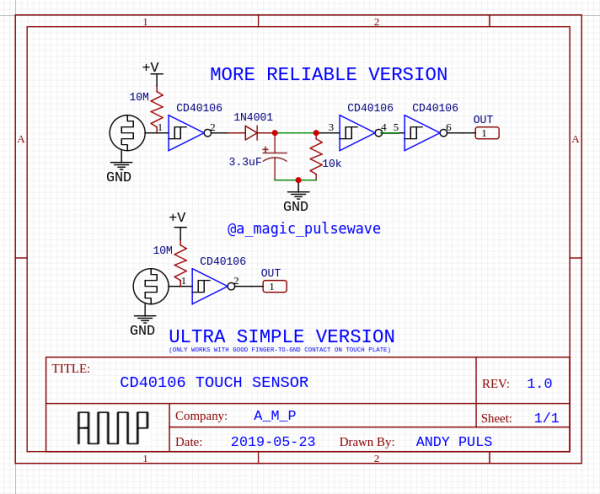
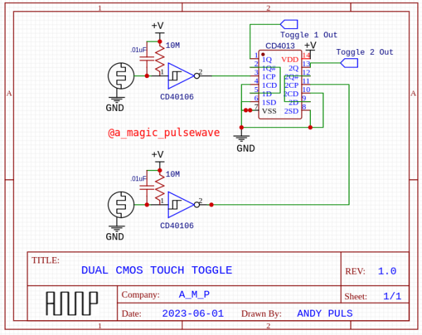
Here are some CMOS touch switches I've come up with and used quite a bit.
The 40106 ones just output a high logic when the touch plate is touched. To work, your touch plate needs to have two conductors, one to cmos input and the other to gnd, which are bridged by your finger. The simple version actually works very reliably as long as you have a pretty narrow gap between the two conductors.
The more reliable version actually works pretty decent even without good GND contact because it will take the 60HZ buzz you are inducing and then filter out the low side of the wave for a continuous positive output while touching.
The toggle one uses a similar 40106 touch sensor as an input but uses a 4013 to output an alternating signal for each time it is touched. The .01uF capacitor on the input helps cut noise/debounce for a more reliable toggling experience.
EDIT: also reading your plans for your synth/sequencer more closely, you might want to check out the Touch Tones and Melody Oracle (and Star Song which I just posted about). All of them use a 4051 pot switching scheme, and expand it into octave divisions using a 4040.
Touch Tones
https://electro-music.com/forum/post-440653.html
and the Melody Oracle:
https://electro-music.com/forum/topic-68735.html
| Description: |
|
| Filesize: |
69.92 KB |
| Viewed: |
129 Time(s) |
| This image has been reduced to fit the page. Click on it to enlarge. |
|
| Description: |
|
| Filesize: |
66.12 KB |
| Viewed: |
117 Time(s) |
| This image has been reduced to fit the page. Click on it to enlarge. |
|
_________________
∆ A.M.P. ESOTERIC ELECTRONICS ∆ |
|
|
Back to top
|
|
|
ianbax
Joined: Apr 20, 2022
Posts: 42
Location: Sheffield, UK
|
| Posted: Mon Jun 12, 2023 1:20 am Post subject:
|
|
|
| Ah thanks - I'll check those out too. Interesting to see how to the 60hz pulse wave can be rectified with the 4013 flip flop. |
|
|
Back to top
|
|
|
elektrouwe
Joined: May 27, 2012
Posts: 146
Location: Germany
|
| Posted: Tue Jun 13, 2023 12:18 am Post subject:
|
|
|
| all circuits shown here are missing ESD protection ! Do yourself a favour and add a >=100k series resistor between CMOS input and touch input components. A 4000CMOS is "ancient technology" and you can easily destroy a chip by e.g. walking with rubber/plastic sole shoes and then touching an unprotected input. Often chip failure happens 1..2 years after the ESD event. Many companies learnt this the hard way, although information was already available in the early 70s data books. |
|
|
Back to top
|
|
|
|

 Forum index » DIY Hardware and Software » Lunettas - circuits inspired by Stanley Lunetta
