| Author |
Message |
andrewF

Joined: Dec 29, 2006
Posts: 1176
Location: australia
Audio files: 4
|
 Posted: Thu Oct 09, 2008 11:05 pm Post subject:
CMOS chaos generator Posted: Thu Oct 09, 2008 11:05 pm Post subject:
CMOS chaos generator
Subject description: experimental cct |
  |
|
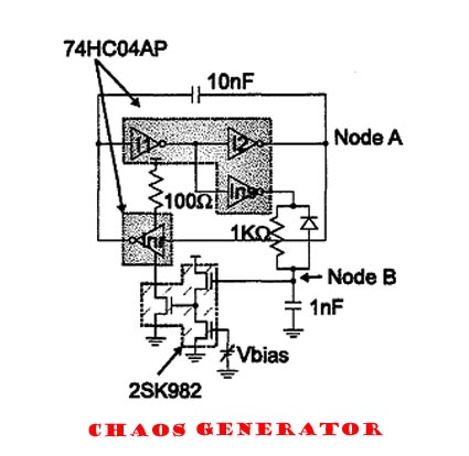
I've had this cct in my ahem 'files' for a while and recently breadboarded it. I think it came from a Japanese research paper, will try to find the article.
Basically it is a regular inverter oscillator but one feedback path goes thru an inverter, on a separate chip that has its power supply fluctuated by the output signal. Tap outputs at nodes A&B
You need two inverter chips. I used 4011s wired as inverters, cos i have dozens of them. One chip gets normal power and ground, the other has the 100 Ohm resistor to +V and the 0V goes thru the FETs.
Tried various caps sizes for different operating frequencies. The Vbias pot is just wired as a voltage divider, though put Vbias above approx 3V and it stops working.
Eventually one chip overheated and died, I suspect I burnt the FET gates, but haven't investigated properly.
This cct does produce a chaotic signal that varies with vbias, not a very pretty one like you get from Ian's designs, but who knows, with some refining it may prove to be a great addition for any modular.
My next step is to off the FETs and use a NPN transistor (or a few) on the +V side with the ground pin connected directly to ground. Also needs opamp buffers for the output signals, I found plugging this into a mixer as is affects the operation.
A 4009 inverter would also be interesting as there is a separate pin that controls the voltage levels of the output signals. I have some of these but they are out of production so not really an option worth pursuing.
Anyway it is an easy cct to breadboard, would love to hear some other suggestions.
| Description: |
|
| Filesize: |
32.52 KB |
| Viewed: |
10137 Time(s) |
|
|
|
|
Back to top
|
|
 |
loss1234

Joined: Jul 24, 2007
Posts: 1536
Location: nyc
Audio files: 41
|
|
|
Back to top
|
|
|
andrewF
Joined: Dec 29, 2006
Posts: 1176
Location: australia
Audio files: 4
|
| Posted: Fri Oct 10, 2008 10:43 pm Post subject:
|
|
|
You can tap output signals from nodes A&B, but these are not buffered, I found when I hooked these up to a mixer for a listen, the signal changed (on the 'scope).
If this is for a lunetta synth, it would be unethical to add buffering  if it is for jamming into regular synth modules i recommend adding some op-amp buffers, partly to 'isolate' the cct and partly to get the signals at voltage levels that suit your synth. if it is for jamming into regular synth modules i recommend adding some op-amp buffers, partly to 'isolate' the cct and partly to get the signals at voltage levels that suit your synth.
The 2sk982 is an N-channel mosfet. I happened to have a dozen of them so easy for me. They are nothing special, so any general purpose n-channel should do the job.
that being said, i am considering replacing the fets with npn transistors, and putting them on the +V pin rather than the ground, seems a rather abusive way to treat a chip by bunging up its ground pin. This chip overheated and died on me after running for 30 minutes or so. Bit like gluing up someones ass and then force feeding them. Maybe it won't work by controlling the +V pin, but will find out.
This doesn't sound anything like Ian's ccts, mostly sounds like noise so far. Needs plenty of R&D  |
|
|
Back to top
|
|
|
loss1234
Joined: Jul 24, 2007
Posts: 1536
Location: nyc
Audio files: 41
|
|
|
Back to top
|
|
|
andrewF
Joined: Dec 29, 2006
Posts: 1176
Location: australia
Audio files: 4
|
| Posted: Sat Oct 11, 2008 9:02 am Post subject:
|
|
|
enjoy, it definitely does work as is.
i used 12V supply, the 3V mentioned was just an approx figure for maximum Vbias. Still try different power supply voltages, might be interesting. |
|
|
Back to top
|
|
|
|

 Forum index » DIY Hardware and Software » Lunettas - circuits inspired by Stanley Lunetta

