| Author |
Message |
PERFORMANCE
Joined: Jun 11, 2020
Posts: 36
Location: Germany
|
 Posted: Sun Mar 28, 2021 7:59 am Post subject:
Performance‘s building and troubleshooting thread Posted: Sun Mar 28, 2021 7:59 am Post subject:
Performance‘s building and troubleshooting thread
Subject description: Scott Bernardi VC Delay |
  |
|
EDIT: instead of making another thread whenever I have trouble getting my stuff working I just edit the sub-title including what’s troublesome at the moment so there’s no more spam than necessary!
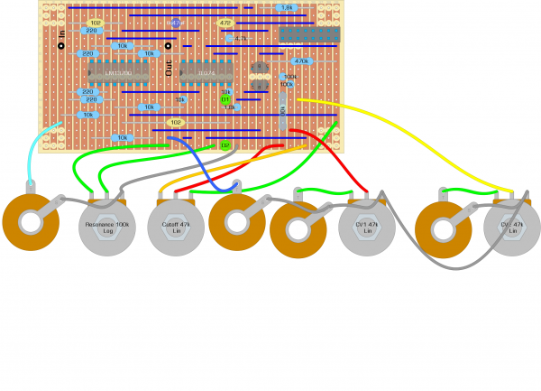
Here’s how it started (MS-20 VCF is SOLVED but will get a complete rebuild asap....): [...]build a MS-20 filter clone for my eurorack synth and as so many I chose René Schmitz schematic from his fabulous SDIY page. It is built on stripboard and uses one LM13700 instead of CA3080. Both ICs (LM13700 and TL074) get their power correctly and cutoff and both channels of CV-control seem to behave properly as well. After some minor troubleshooting it started working so I thought it would be okay but the resonance pot is not doing anything at all (or just very, very little - almost unnoticable). Here‘s the thing: it doesn‘t scream at all! I‘ve checked the schematic and my soldering over and over again - it just doesn‘t work although it should. The only thing that‘s different from René‘s version ist the fact that I used 100kb-pots instead of 47kb but since cutoff control and CV attenuation work very properly this should not be the reason for its misbehavior. The resonance pot is 100ka as it should. One thing I noticed, though, is that the green LEDs won‘t light up (only when I accidentally touched the board and shorted something while in stalling it into the rack). Any ideas or solutions? I already thought about changing the resistor value for the one going from the opamp terminal where the LEDs are connected to ground, changing the value of the resonance pot or changing the LEDs for red ones or 1n4148s as in the original design but that‘s it. What could I measure, what could I change to make it work? Cheers and thanks to all.
Here‘s a link to a video I made to demonstrate the problem. Upper pot obviously is cutoff, middle pot is resonance, lower pots are CV-attenuators. Other modules involved are Doepfer A-110-1 and a dual LFO based on Niklas Rönnberg‘s design.
https://youtu.be/AvKQ7cnTzMY
Last edited by PERFORMANCE on Thu Mar 24, 2022 9:31 pm; edited 6 times in total |
|
|
Back to top
|
|
 |
dk
Joined: Feb 12, 2019
Posts: 115
Location: Europe
|
| Posted: Sun Mar 28, 2021 9:39 am Post subject:
|
|
|
I built Takeda's version, which looks part for part the same (at least after a quick glance). Screaming is definitely not a problem 
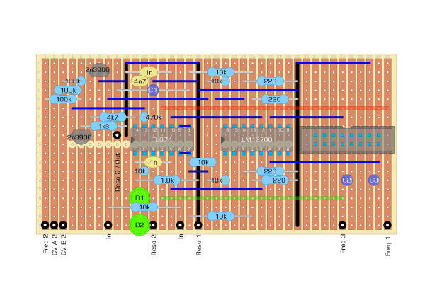
In your video it sounds like the resonance isn't working at all... which layout did you use? There is at least one floating around with errors on it, specifically where the resonance feedback resistor and diodes/LED's aren't going between the correct rows...
_________________
Horrors Of Dial-Up! on Facebook
Horrors Of Dial-Up! on Instagram |
|
|
Back to top
|
|
|
PERFORMANCE
Joined: Jun 11, 2020
Posts: 36
Location: Germany
|
|
|
Back to top
|
|
|
dk
Joined: Feb 12, 2019
Posts: 115
Location: Europe
|
| Posted: Mon Mar 29, 2021 1:32 am Post subject:
|
|
|
Ok, scanning over it this morning on my phone I didn't pick up any glaring errors, but...
The first thing I noticed is a lack of power filtering. I don't know how critical it is for this circuit, but generally having a pair of caps (10u-47u) strapped across your power rails where they connect to the board is good practice. You should probably have decoupling caps (100n?) where power meets your chips for both rails.
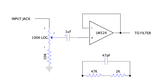
Also, on my clone, I have slightly different values around the resonance amp. I actually have less gain there than you should, so I don't think that's the problem. When I hit mine with loads of signal, though, it won't squeal no matter what I do. Have you tried leaving the input disconnected and turning the resonance all the way up? I have a pot with a voltage follower in front of mine to make the input adjustable (see attachment)... with the original values used (100k from input to OTA and 220r to ground), it squealed like crazy but the signal level was too low. I think now I have a 4k7 resistor there (where you have 10k), and for the last 1/3rd of the the pot travel the input signal overpowers the resonance quite a bit. It is audible that I'm adjusting the resonance pot, but it's nothing close to self oscillation.
| Description: |
|
| Filesize: |
32.27 KB |
| Viewed: |
189 Time(s) |
| This image has been reduced to fit the page. Click on it to enlarge. |
|
_________________
Horrors Of Dial-Up! on Facebook
Horrors Of Dial-Up! on Instagram |
|
|
Back to top
|
|
|
PERFORMANCE
Joined: Jun 11, 2020
Posts: 36
Location: Germany
|
| Posted: Mon Mar 29, 2021 2:13 am Post subject:
|
|
|
| dk wrote: | | The first thing I noticed is a lack of power filtering. I don't know how critical it is for this circuit, but generally having a pair of caps (10u-47u) strapped across your power rails where they connect to the board is good practice. You should probably have decoupling caps (100n?) where power meets your chips for both rails. |
Hey! Yes, I should really do that, I did on most of the other builds but didn‘t on this one for no reason - easy fix, though!
Regarding self oscillation: that‘s a thing I wondered about as well. It doesn‘t self oscillate but I‘ll switch a couple of resistors tonight and see what it does to the circuit.
Also thanks for recommending the input buffer - I‘ll simulate that with an attenuater! |
|
|
Back to top
|
|
|
dk
Joined: Feb 12, 2019
Posts: 115
Location: Europe
|
| Posted: Mon Mar 29, 2021 3:29 am Post subject:
|
|
|
Just for reference, then, the resistors I have around the resonance amp are a 4k7 from inverted input to ground and a 5k trim pot in parallel with the LED's. I have green LED's in mine. The original Korg units have 10k strapped in parallel to the LED's and 2k2 + a 2k trimmer from the inverted input to ground. That means your version should have more gain than both the original and my own, unless you've accidentally switched those two resistors?
I would still try getting it to self-oscillate with nothing hooked up to the input first, though. The original Korg didn't have the kind of output levels you typically see in Eurorack, so I'm guessing you just need to pad the input down a bit to keep the OTA from being overloaded.
_________________
Horrors Of Dial-Up! on Facebook
Horrors Of Dial-Up! on Instagram |
|
|
Back to top
|
|
|
PERFORMANCE
Joined: Jun 11, 2020
Posts: 36
Location: Germany
|
| Posted: Mon Mar 29, 2021 9:58 am Post subject:
|
|
|
Hey!
Thanks again for all the replies. My agenda for tonight looks like this:
- attenuating the input and see if it resonates properly
- change the resistor values around at the resonating op-amp
- change the opamp (I also have LM324s lying around, maybe that helps)
- measure/ change the reso-pot (although it was brand new when installing this might also much unlikely be a cause of error)
also: cleaning the power with caps!
I'll keep the audience updated.... |
|
|
Back to top
|
|
|
dk
Joined: Feb 12, 2019
Posts: 115
Location: Europe
|
| Posted: Mon Mar 29, 2021 12:19 pm Post subject:
|
|
|
Sounds good!
Feel free to try with no signal first, though. If it doesn't resonate that way, then the problem will definitely require 'fixing' something in the circuit you've got going on.
As for the op-amp, I think I'm using a TL082. I think in this situation, it's virtually identical to a TL072 (slightly different noise floor, otherwise the same). My buffer only had LM324 written there as it was on the same board as a level shifter run off a single supply, but I'm not sure that chip belongs directly in the filter circuit.... at the very least it's probably not advantageous compared with using the onboard buffers on the LM13700.
If you can't get self-oscillation without any input signal present, then go to town on the resonance amp section. It's gotta be something there. A micro solder bridge. Pot acting up. Resistors reversed. Whatever, but I'll bet it's there somewhere.
Best of luck!
_________________
Horrors Of Dial-Up! on Facebook
Horrors Of Dial-Up! on Instagram |
|
|
Back to top
|
|
|
PERFORMANCE
Joined: Jun 11, 2020
Posts: 36
Location: Germany
|
| Posted: Thu Apr 01, 2021 4:21 pm Post subject:
|
|
|
| Okay...I got it to scream now. I build a little patchbay with female pin headers to change both resistors on the resonance-amp and the LEDs. Didn't work with any of the resistors I treid BUT worked when I entirely ditched the resistor in parallel with the LEDs....now gotta work around the fact that it's starting to scream at 1/3 of the Reso Pot! |
|
|
Back to top
|
|
|
dk
Joined: Feb 12, 2019
Posts: 115
Location: Europe
|
| Posted: Fri Apr 02, 2021 1:40 pm Post subject:
|
|
|
Good to hear!
Perhaps try a trim pot in place of the resistor parallel to the LED's so you can adjust the onset of squealing?
_________________
Horrors Of Dial-Up! on Facebook
Horrors Of Dial-Up! on Instagram |
|
|
Back to top
|
|
|
PERFORMANCE
Joined: Jun 11, 2020
Posts: 36
Location: Germany
|
| Posted: Sun Apr 04, 2021 7:38 pm Post subject:
|
|
|
| dk wrote: | Good to hear!
Perhaps try a trim pot in place of the resistor parallel to the LED's so you can adjust the onset of squealing? |
I will try that. I like the overall sound right now so there actually is no need to change it right now. What really bothers me is the fact that I don't really understand what is going on with the resistor in parallel and why the resonance only seems to work at all when it's omitted (I've tried many values just down to 80ohms and it still only started working when the resistor was bridged/ omitted). Anyway - thanks again very much for your help, I'll post a video of its operation soon!
Next module btw will be a dual "Fastest Envelope In The West", also by René. |
|
|
Back to top
|
|
|
PERFORMANCE
Joined: Jun 11, 2020
Posts: 36
Location: Germany
|
| Posted: Wed Apr 14, 2021 2:37 am Post subject:
|
|
|
| okay, update: after working really great the filter suddenly died. i didn't have the chance to properly troubleshoot it but i suspect there's a mechanical failure in the pcb due to the massive changes i made to get it work properly. i'll build another one from the ground up because i love the sound, i will keep you updated on this and finally post a demo. meanwhile there are other modules scheduled, a dual EG, baby 8 sequencer, dual VCA, more mixers and buffers and i'm currently designing a stripboard benjolin (but that's a big thing...) |
|
|
Back to top
|
|
|
PERFORMANCE
Joined: Jun 11, 2020
Posts: 36
Location: Germany
|
Posted: Sat Apr 24, 2021 10:28 pm Post subject:
Fastest Envelope in the West
Subject description: René Schmitz‘ classic |
|
|
So, the MS-20 VCF did eventually work almost properly but died when I accidentally plugged something around somehow.....anyway, due to all the troubleshooting and rebuilding the stripboard had become a mess anyway so I will build another board from scratch and make it a clean build this time.
MEANWHILE: another Schmitzbit is bothering me - a dual „Fastest Envelope In The West“. Once again I designed and carefully counter checked the stripboard layout with the schematic, then soldered everyhting together (the first EG so far, not the second, almost identical board), made a crappy panel, attached all the parts plus additional LEDs and got it running sort of...
Attack and Release do work properly (although I need to change the direction of the pots still) but decay and sustain don‘t respond to any change in knob position. It feels like full sustain all the time. Gate time is having an impact on the length of the sustained part but decay is not noticeable and the level of sustain also doesn‘t change with the turn of a knob. Any ideas? Haven‘t measured any voltages yet but will within the next few days.
I feel a little cursed, btw, because the first ADSR I wanted to build - Nicolas‘ ADSR With looping function and such - also worked kind of but never really did what it was supposed to do (it‘s the only module so far that has been entirely neglected - 8 other modules over the last few weeks have been more or less succesfully built!). So if you know your way around magic in SDIY please destroy that curse! If you‘re a muggle please help with your expertise in electronics! |
|
|
Back to top
|
|
|
gabbagabi

Joined: Nov 29, 2008
Posts: 652
Location: Berlin by n8
Audio files: 23
|
| Posted: Sun Apr 25, 2021 1:29 am Post subject:
|
|
|
I had a chat with my Healer,
After throwing some resistors and two obsolete Transistors (pnp!) Into some ferric Chlorid,
He read out that Long and intensive Sessions on
The breadboard before and while soldering
Can Break the curse
Wtf where is this smoke coming from ? |
|
|
Back to top
|
|
|
PERFORMANCE
Joined: Jun 11, 2020
Posts: 36
Location: Germany
|
| Posted: Wed May 12, 2021 10:28 pm Post subject:
|
|
|
| gabbagabi wrote: | I had a chat with my Healer,
After throwing some resistors and two obsolete Transistors (pnp!) Into some ferric Chlorid,
He read out that Long and intensive Sessions on
The breadboard before and while soldering
Can Break the curse
Wtf where is this smoke coming from ? |
Haha, didn't react on this yet - sorry! Thanks for talking to your healer. As so often destiny had already been fulfilled before I noticed - the first of both envelopes (I first built one and tested it, then built the other one and sandwiched both stripboards behind an 8 hp eurorack panel containing all the ADSR knobs and Gate inputs and EG outputs) did actually work correctly in the first place - I just didn't properly give it the "right" gates and got confused because the pots were soldered in the wrong way around. Now both work like a charm and can react really snappy as they are supposed to!
Next up ist the rebuild of the Renè Schmitz MS-20 VCF, followed by a dual MFOS VCA from scratch, some more buffered multiples, another mixer and a Baby 8 sequencer. Hopefully until June I will be also able to at least design a stripboard benjolin based on Epoch Modular's schematic and a Scott Bernardi VC Delay (the later would be so great to have). On the non modular side there still is an already designed Boss DS-1 clone and a PT2399-based Chorus Pedal scheduled for the upcoming weeks...gotta make the best of the hopefully last weeks of lockdown and before finally getting vaccinated. |
|
|
Back to top
|
|
|
PERFORMANCE
Joined: Jun 11, 2020
Posts: 36
Location: Germany
|
| Posted: Sat May 15, 2021 9:00 am Post subject:
|
|
|
Okay, okay.....it really must be cursed. The second iteration of my MS-20 VCF based on Renè Schmitz's design behaved the same as the first did, so I went through all the troubles but this time didn't even get it to scream at all.......needs another design, I guess. Maybe I should also just stick to somebody elses stipbad layout - but most of them are too spacious. Or does anybody of you have a stripboard layout of that filter suitable for eurorack levels (power and audio) on a 100x50mm board (or even smaller)?
Meanwhile I'm going to concentrate on other modules to not fall into frustration over this. |
|
|
Back to top
|
|
|
gabbagabi
Joined: Nov 29, 2008
Posts: 652
Location: Berlin by n8
Audio files: 23
|
| Posted: Sat May 15, 2021 11:56 am Post subject:
|
|
|
Sad to hear,
but may you should really consider the ever repeated Phrase "breadboard first" ? |
|
|
Back to top
|
|
|
PERFORMANCE
Joined: Jun 11, 2020
Posts: 36
Location: Germany
|
| Posted: Sat May 15, 2021 8:15 pm Post subject:
|
|
|
| gabbagabi wrote: | Sad to hear,
but may you should really consider the ever repeated Phrase "breadboard first" ? |
hrrrrrnnggggggggggggggggggg..........wanted to build a "bench supply" for that purpose anyway but i hate those flimsy breadboards....but it's a good idea, I even invested in some better quality breadboards recently. |
|
|
Back to top
|
|
|
PERFORMANCE
Joined: Jun 11, 2020
Posts: 36
Location: Germany
|
|
|
Back to top
|
|
|
PERFORMANCE
Joined: Jun 11, 2020
Posts: 36
Location: Germany
|
| Posted: Sat Jun 05, 2021 8:50 pm Post subject:
|
|
|
| PERFORMANCE wrote: | okay, bench supply is ready and already helped a lot troubleshooting another module. Now I'm gonna give the MS20 a thrid try. I will breadboard it first this time but also already made a different design.
See below! |
well, already figured out some errors (input, lm13700 power...). |
|
|
Back to top
|
|
|
PERFORMANCE
Joined: Jun 11, 2020
Posts: 36
Location: Germany
|
| Posted: Mon Feb 07, 2022 6:57 pm Post subject:
|
|
|
People of this corner of the internet - I finally managed to build a working iteration of René Schmitz MS20 filter. 
I redesigned my stripboard once again (Vers. 4.0) and this time did some serious troubleshooting afterwards without giving up. I don't know why this had been so hard previously but it finally works - great sound, fully closing and opening over the whole cutoff range, great resonance (from about 12 o'clock it starts screaming but is finely adjustable), CV control works great......I guess one of the next side-projects will be another one and then I'll put both together behind a common panel to have that classic BP-configuration.
Also rebuilt a dual LFO and sorted out a new way to mount my stripboards behind the panels - using two threaded M3 rods cut to length, coated with shrinking tube and mounted onto bolt spacers. between those to rods the stripboard (50x100 cut to minimal size) is then secured with zip ties. I'll post a picture once I get back into the studio.
Next projects will be a renewal of my otherwise nice working Baby8 - only the individual triggers/ gates don't work properly. If every second is switched on it works, if several adjacent steps are switched on only the first will get triggered. I suspect that's because I was lazy not building the entire gate/trigger circuit in fonik's updated schematic. also reset and manual step don't work properly, hope to solve that in parallel.
besides that I have 30+ potential projects in line - modules and effect pedals alike. Next I'll give a dual MFOS VCA on stripboard a try, a Scott Bernardi VC Delay, a Benjolin, a PT2399 chorus, a Boss DS-1 clone, a Big Muff Fuzz clone, an "Easyvibe", another clock divider (couldn't get Niklas Rönnberg's version of fonik's working, will try the original now), an electric druid VCO (once the chips get available again), a stripboard version of MI EARS, a Synthacon Filter...phew!
Kit's I'm planning to purchase and build are 4ms PEG, FoH Plague Bearer (love that, sold my first years ago) and Music Thing Modular Turing Machine 2.
Will keep everybody updated - wanted or not! |
|
|
Back to top
|
|
|
PERFORMANCE
Joined: Jun 11, 2020
Posts: 36
Location: Germany
|
| Posted: Thu Mar 24, 2022 8:35 pm Post subject:
|
|
|
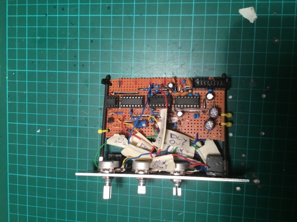
Hey!
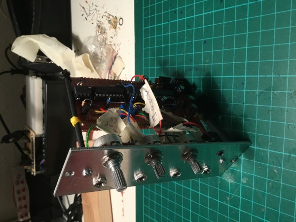
Just wanted to show you my way of mounting PCBs - I think it's quite convenient and easy but is easy to dismantle.
These are M3 threaded rods screwed into M3 standoff bolts (counter fixed by M3 screws from the front panel). The rods themselves are covered in heat shrinking tube and the boars are attached onto the rods via zip ties. Great! It's really cheap but very clean and works great.
The module is a Scott Bernardi VC delay - it's not working yet but I've already traced a couple of (very dumb) mistakes I will hopefully solve soon.
| Description: |
|
| Filesize: |
1.81 MB |
| Viewed: |
83 Time(s) |
| This image has been reduced to fit the page. Click on it to enlarge. |
|
| Description: |
|
| Filesize: |
1.99 MB |
| Viewed: |
83 Time(s) |
| This image has been reduced to fit the page. Click on it to enlarge. |
|
|
|
|
Back to top
|
|
|
|

 Forum index » DIY Hardware and Software