| Author |
Message |
priborpedals
Joined: Aug 13, 2021
Posts: 3
Location: SPb
|
 Posted: Fri Aug 13, 2021 5:52 am Post subject:
Pribor Neofit - super simple CMOS synth Posted: Fri Aug 13, 2021 5:52 am Post subject:
Pribor Neofit - super simple CMOS synth |
  |
|
Hello! Here is my first post here. Sorry if something is not as well as it should as my poor english.
When building simple beating infrabass synth voice I found something different. I didn't found the exact project so I decided to share it and I think Lunettas forum is a best place to do that. It have very small amount of parts and I hope that it could be a nice entry level project.
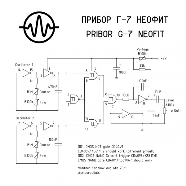
Main idea was very simple - two square wave oscillators multiplied by MS20-style ring modulator. I started with 4049 inverter and 4093 NAND Schmitt trigger just because I had a bucket of both. Schematics was almost the same as if final circuit. But raw multiplied signal is pulse 9V peak-to-peak and I found that simplest way to make it more musical is to put an integrator at the output. This made sound more interesting than simple low pass filter and 100nF capacitor works there very nice but possible to experiment with different values to change triangle shape of output signal. 47nF filtering cap used to cut high frequency noise. Also I decided to make oscillators with different range and coarse/fine tune controls because in low frequencies sound is like amplitude modulated signal but when both oscillators tuned in close frequencies beating sound appears. And funniest thing I discovered than when power off sound didn't disappear simultaneously but frequency and shape is changing when power cam is discharging because of circuit requires very low current so I added voltage drop control also. I used Tesla MHB4049 and ST HCF4093BE and maybe voltage drop will act different with different manufacturers ICs so could be very interesting if anyone will experiment with.
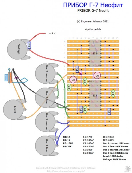
I built that synth on stripboard - maybe layout is not perfect but well fits to 1590B.
Video with scope is here:
https://www.instagram.com/tv/CSb8GrZFk9U/
Hope you'll like it!
Thank you!

| Description: |
|
| Filesize: |
463.73 KB |
| Viewed: |
394 Time(s) |
| This image has been reduced to fit the page. Click on it to enlarge. |
|
| Description: |
|
| Filesize: |
285.19 KB |
| Viewed: |
409 Time(s) |
| This image has been reduced to fit the page. Click on it to enlarge. |
|
|
|
|
Back to top
|
|
 |
wakyct
Joined: Dec 30, 2020
Posts: 105
Location: USA
Audio files: 12
|
| Posted: Sat Aug 14, 2021 1:02 pm Post subject:
|
|
|
Cool, especially liked the sound around 7:20 in the video...nice plans too  |
|
|
Back to top
|
|
|
PHOBoS

Joined: Jan 14, 2010
Posts: 5884
Location: Moon Base
Audio files: 709
|
| Posted: Tue Aug 17, 2021 6:19 pm Post subject:
|
|
|
 
neat little box, nice idea with the integrator.
However, that inverter which has its output connected to ground might not be very happy. Especially if the input is also tied to ground
which means the output is trying to go high. It might have an interesting effect on the sound though and maybe it will survive. When
the current is limited it shouldn't be too bad but otherwise you might want to check if the chip is getting hot.
_________________
"My perf, it's full of holes!"
http://phobos.000space.com/
SoundCloud BandCamp MixCloud Stickney Synthyards Captain Collider Twitch YouTube |
|
|
Back to top
|
|
|
priborpedals
Joined: Aug 13, 2021
Posts: 3
Location: SPb
|
| Posted: Wed Aug 18, 2021 2:48 pm Post subject:
|
|
|
| Reason to connect last inverter's both input or output to ground was to cancel a noise. Maybe with 100n bypass power capacitors and disconnected output is more traditional way to do it, but I like to make all as simple as possible and also i'm not sure that bypass caps will work as should with veroboard. Current is very small - circuit producing sound few seconds more when power off. |
|
|
Back to top
|
|
|
Steveg

Joined: Apr 23, 2015
Posts: 184
Location: Perth, Australia
|
| Posted: Wed Aug 18, 2021 6:55 pm Post subject:
|
|
|
| You would connect the input to ground to prevent noise (otherwise the pin will act like an antenna picking up any stray signal and inverting it). But as PHOBoS points out connecting the output to ground is a really bad idea. Maybe you will get away with it with this chip in cold weather but I wouldn't bet on it in the general case. |
|
|
Back to top
|
|
|
priborpedals
Joined: Aug 13, 2021
Posts: 3
Location: SPb
|
| Posted: Sat Sep 18, 2021 3:21 am Post subject:
|
|
|
I compared the sound when last inverter's output disconnected or connected to ground. When output is disconnected appering glitchy noises on both oscillators outputs, especially when voltage drops. When that output connected to ground waveform became more stable but i noticed a voltage drift between power pins with oscillators frequencies producing pseudo random clicks. No IC heatind was noticed all the time. I did'n measured a current consumption because I have no device to measure less than 10 mA.
I get some modern TI CD4049UBE and tested the circuit - sound became completely different and all the funny pseudo-random noise had lost. So I'm sure that that's all is because of previously used Tesla MHB4049 internal circuit. Unfoftunately I didn't found schematic of exact MHB4049 inverter unit but when compared some datasheets including TI 4049UBE (different datasheet revisions), RCA CD4049A, Fairchild CD4049UBC, Intersil CD4049UBMS and few more, all the internal circuits are different, mostly with diodes at input and positive terminals. Also MHB4049 could be a buffered inverter like Philips HEF4049B or Toshiba TC4049BP.
When I will check some more different 4049's I'll update the schematic. |
|
|
Back to top
|
|
|
PHOBoS
Joined: Jan 14, 2010
Posts: 5884
Location: Moon Base
Audio files: 709
|
|
|
Back to top
|
|
|
|

 Forum index » DIY Hardware and Software » Lunettas - circuits inspired by Stanley Lunetta

