| Author |
Message |
ianbax
Joined: Apr 20, 2022
Posts: 42
Location: Sheffield, UK
|
|
|
Back to top
|
|
 |
ianbax
Joined: Apr 20, 2022
Posts: 42
Location: Sheffield, UK
|
 Posted: Mon Oct 28, 2024 12:55 pm Post subject: Posted: Mon Oct 28, 2024 12:55 pm Post subject:
|
  |
|
Solved! - Perhaps people would like to see how it's possible. It does involve using an op amp (a couple actually) which makes it moot whether it's a lunetta thing I suppose. I did wonder, half way through doing it, why I didn't just build a 'proper' triangle oscillator. I persisted because the rest of my set up is all single supply at 5v and this oscillator gives me a different voice that still interacts with my sequencer and 'vactrol controlled amplitude' and so on.
I found the answer here
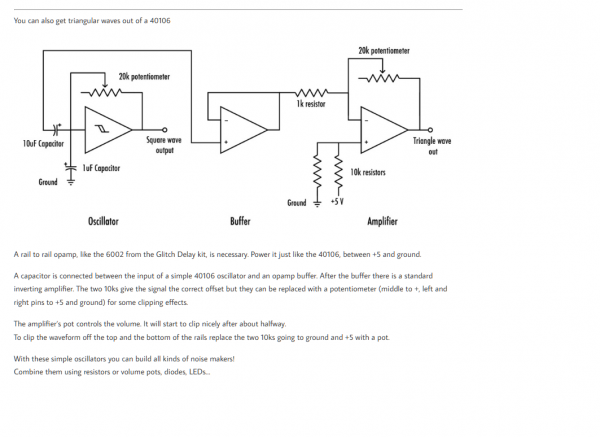
https://bleeplabs.com/rad-fi-analog/
A 6002 op amp is used because it can go rail to rail. Here's their circuit first.
Then my modifications.
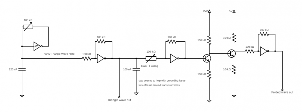
I swapped the gain control to be on the input of the op amp, rather than the feedback path. This way it can be vactrol controlled (because more light == more gain seemed more intuitive to me). I have a envelope generator that is a fading up and down led vactrol so it works with that.
The feedback path is a trimmer that can be set so the gain control shapes from triangle (or saw - see next point) to square wave. At minimum gain the triangle can be set with the trimmer to just touch the rails with a scope.
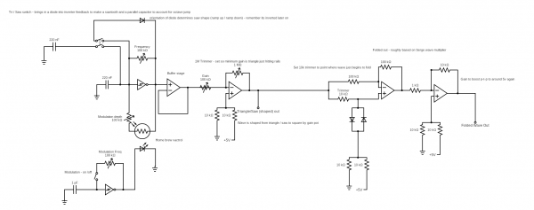
The wave is switchable between saw and triangle. A DPDT switch puts a diode in the feedback path of the inverter as per Elliot Williams:
https://hackaday.com/2015/03/09/logic-noise-sawing-away-with-analog-waveforms/
BUT also puts an additional capacitor in parallel to the first to account for the octave jump that the diode creates (because the capacitor drains in half the time?)
The wave can be modulated by a slower oscillator - capacitor of 1uf gave me good FM type results that only just go sub-audio but it's just a suggested value. This is linked to a LDR-LED homebrew vactrol which goes 'across' the frequency pot of the first oscillator. I actually used a DPDT in my final design - to break the feedback path of the modulation oscillator and the connection of the LDR. The modulation depth pot in series with the LDR sets - I think - the maximum variation it can add to the frequency. This is important - put straight across the frequency pot the LDR swings min to max (100k).
Almost all these modifications are the results of hands on experimentation so my explanations may not be totally accurate!
Finally I tried to get the wavefolding with transistor working but it just didn't work (something to do with the op amplified wave already being 5v peak to peak???) as a last roll of the dice I tried the Serge op amp folding as explained by Aaron Lanterman:
https://www.youtube.com/watch?v=zL9ao3Uc3Yk
With a bit of tweaking - e.g. sending the diodes to an offset ground point I managed to get a bit of a wave folding effect - although it looks a bit odd on the scope. The 10k input trimmer had to be set to the point where the wave was just folding. At full gain it sort of goes into an odd spiky square. Aurally the 'overtones being added' effect is there so I was happy.
What I couldn't get to work was multiple stages...no idea why!
The final stage adds 10x gain (1k input, 10k feedback) to get the wave back to 5v peak to peak ish. You could be more sophisticated and add a trimmer here too.
Hopefully a fun circuit for someone. It was fun to breadboard up.
| Description: |
|
| Filesize: |
115.8 KB |
| Viewed: |
123 Time(s) |
| This image has been reduced to fit the page. Click on it to enlarge. |
|
| Description: |
|
| Filesize: |
64.3 KB |
| Viewed: |
142 Time(s) |
| This image has been reduced to fit the page. Click on it to enlarge. |
|
|
|
|
Back to top
|
|
|
zaphod betamax
Joined: Nov 27, 2020
Posts: 62
Location: sarnia
|
| Posted: Wed Oct 30, 2024 7:36 am Post subject:
|
|
|
If you wanted to keep it all Lunetta why not use a CD4069UB
as an amplifier with AC coupling and gain resistors. |
|
|
Back to top
|
|
|
ianbax
Joined: Apr 20, 2022
Posts: 42
Location: Sheffield, UK
|
| Posted: Wed Oct 30, 2024 11:40 am Post subject:
|
|
|
Like I said in the first post - no matter what gain I used I couldn't get a decent signal out of the 4049 (which is what I had Vs a 4069 but I don't think it's significant)
Was AC coupling what I was missing? |
|
|
Back to top
|
|
|
PHOBoS

Joined: Jan 14, 2010
Posts: 5881
Location: Moon Base
Audio files: 709
|
| Posted: Wed Oct 30, 2024 12:29 pm Post subject:
|
|
|
sorry I am late to the party,.. 
I never really messed around much with the 4069UB (or 4049) but I don't think AC coupling would help you out.
As a matter of fact I believe that one of the reasons you see the 4069UB used as an amp in circuits like this is
that they are already correctly biased to work with a single supply. Assuming the signal you are working with
is biased around half that supply voltage.
The original 'triangle' signal will oscillate somewhere between 1/3 and 2/3 of the supply voltage caused by the
hysteresis of the 40106 schmitt trigger gates. (more precise values can likely be found in the datasheet).
With a 5V supply that would give you an amplitude of about 1.7V which is indeed a lot lower than a square
wave with a 5V amplitude. Also the average voltage is lower because it is a triangle (compare the surface area
of a triangle with the surface area of a square). And then there is just the sound itself which for a triangle
wave sounds much duller than a square wave (even if they have the same amplitude) so that would explain
why it sounds so soft.
Boosting it either with an opamp or one of those unbuffered gates works but I think that you're biggest problem
here is that with a 5V supply you don't really have much headroom. An LM358 is indeed very useful with a single
supply because the output can get very close to 0V however it can't get nearly as close to the supply voltage and
it gets worse if that voltage is already fairly low. Unbuffered gates like the 4069UB also have a limited output range
and I recall that it also has some weird non linear behavior above a certain amplitude.
(I think that's at least partially responsible for the characteristics of the WASP filter).
As you already mentioned the 6002 is a rail-to-rail opamp so that can help you out. Another solution could be to
use a higher supply voltage for buffering. If you keep the oscillator powered by 5V you could easily get the output
amplitude high enough with an LM358 powered by 12V. I am assuming you'd rather have everything powered by
5V though.
_________________
"My perf, it's full of holes!"
http://phobos.000space.com/
SoundCloud BandCamp MixCloud Stickney Synthyards Captain Collider Twitch YouTube |
|
|
Back to top
|
|
|
ianbax
Joined: Apr 20, 2022
Posts: 42
Location: Sheffield, UK
|
| Posted: Sat Nov 02, 2024 3:26 am Post subject:
|
|
|
Many thanks for the explanations PHOBOS - it's useful to understand why the LM358 and 4049 didn't cut it in this instance.
I'm not tying myself in knots about my circuit not necessarily being 'pure lunetta' by using an op amp - although I know there are some philosophical debates about that. It's more of a feeling that I'm trying to fit a square peg in a round hole or reinvent the wheel - if you digress to triangle, saw tooth and sine waves you may as well ditch the 5v single supply and just build some 'proper' dual supply synth circuits. Still, breadboarding and experimenting is half the point of doing this - otherwise I'd just by a bunch of pcbs and solder them up.
I do sort of regret settling on 5v - when I first started building the whole idea was to interface with an arduino at some point so I settled on 5v as a standard, it has caused some problems along the way! Would have been much easier to just step the voltage down at that one point! |
|
|
Back to top
|
|
|
|

 Forum index » DIY Hardware and Software » Lunettas - circuits inspired by Stanley Lunetta