electro-music.com   Dedicated to experimental electro-acoustic
and electronic music
 
    Front Page  |  Radio
 |  Media  |  Forum  |  Wiki  |  Links
Forum with support of Syndicator RSS
 FAQFAQ   CalendarCalendar   SearchSearch   MemberlistMemberlist   UsergroupsUsergroups   LinksLinks
 RegisterRegister   ProfileProfile   Log in to check your private messagesLog in to check your private messages   Log inLog in  Chat RoomChat Room 
go to the radio page Live at electro-music.com radio 1 Please visit the chat
  host / artist show at your time
today> Twyndyllyngs tonight Chez Mosc
poster
 Forum index » DIY Hardware and Software
Trigger CR Question Nr 2
Post new topic   Reply to topic Moderators: jksuperstar, Scott Stites, Uncle Krunkus
Page 1 of 1 [7 Posts]
View unread posts
View new posts in the last week
Mark the topic unread :: View previous topic :: View next topic
Author Message
zipzap


Joined: Nov 22, 2005
Posts: 559
Location: germany
Audio files: 24

PostPosted: Sat Apr 22, 2006 1:56 am    Post subject: Trigger CR Question Nr 2
Subject description: Almost finished the sequencer
Reply with quote  Mark this post and the followings unread

Hi Forum
The shematic down there shows the logic for the trigger rows of my sequencer. I´ve been trying around the A-Version (for about a year, this was my first real project), it was never running really good.
Now i´m going for the B-Option, wich is really unshakable. Independent from clockspeed, duty cycle, delays.
I found out that i don´t need the Buffers, which makes things even easier.
Question is: Do i need the resistors going to ground between the cab and the diode? It´s working well without, but i don´t know if i maybe risc something like creating negative voltages that cannot be shortened or something else that i can´t even imagine.
Anybody knows about this?


sequencer.jpg
 Description:
 Filesize:  10.71 KB
 Viewed:  11497 Time(s)

sequencer.jpg


Last edited by zipzap on Sun Apr 23, 2006 1:39 pm; edited 1 time in total
Back to top
View user's profile Send private message
blue hell
Site Admin


Joined: Apr 03, 2004
Posts: 24514
Location: The Netherlands, Enschede
Audio files: 298
G2 patch files: 320

PostPosted: Sat Apr 22, 2006 3:35 am    Post subject: Reply with quote  Mark this post and the followings unread

Leaving out the resistors in principle makes the input voltage for the gates undefined, which could cause occasional trouble. Also the impedance on the port inputs is very high, and it is lowered by putting the resistors in, this means it will happen less often that your refrigerator is making the sync pulses Very Happy

The wrong voltages you mention will happen with or without the resistors, but when the capacitors have small values (lets say some tens of nF's) the built in protection diodes on the gates' inputs will deal with that. For large capacitors you'd want to have external protection diodes and/or current limiting resistors.

The thing is that when you blow the internal protection diodes you'll not notice much, the part will become slower and it will draw more current on its input but it will probably just continue working (as the gates are not exactly stressed to their speed limits in this application).

_________________
Jan
also .. could someone please turn down the thermostat a bit.
Posted Image, might have been reduced in size. Click Image to view fullscreen.
Back to top
View user's profile Send private message Visit poster's website
zipzap


Joined: Nov 22, 2005
Posts: 559
Location: germany
Audio files: 24

PostPosted: Sat Apr 22, 2006 10:16 am    Post subject: Reply with quote  Mark this post and the followings unread

Hello to Hell
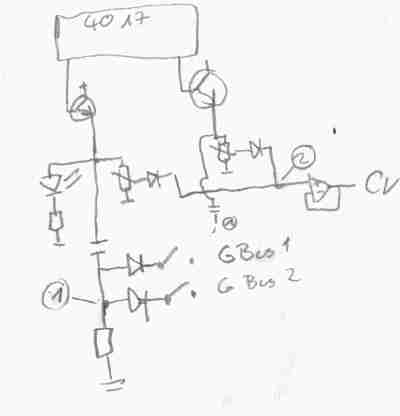
Of course with gates i need pulldown resistors. I think there´s some misunderstanding. It´s the Gates i want to get rid of. So the thing in the shematic with the mark 40?? should be left away.
The cab is going direcly through the diode to the Gatebus. That goes to an pulldown resistor and a 4538 monostable multivib.
i just don´t know if i need a resistor between the cab and the diode for some reason.
The cab i juse right now is 22nf. [/quote]
Back to top
View user's profile Send private message
blue hell
Site Admin


Joined: Apr 03, 2004
Posts: 24514
Location: The Netherlands, Enschede
Audio files: 298
G2 patch files: 320

PostPosted: Sat Apr 22, 2006 10:53 am    Post subject: Reply with quote  Mark this post and the followings unread

Ok, yes I misunderstood then.

Without the pulldowns on the anode side of the diode it's not quite clear how current should flow on the negative edge of the input pulse, it would have to be the diode leakage which is small and not very accurate. On the next upgoing edge the capacitor will not be full discharged and so some extra current will flow into the bus line then and (so) the voltage will be higher. Doesn't seem to be a problem to me except that the pulses will have a less (probably mariginal) wel defined width.

I was thinking though, when you leave the gates in but make them open collector gates or TTL compatible and let them be inverting ones and then use an inverting amp after the bus you'd be able to leave the diodes out - that would save some work and some cost. The bus will be pulled low then instead of driven high, so you'll need a pull up on the bus instead of a pull down.

_________________
Jan
also .. could someone please turn down the thermostat a bit.
Posted Image, might have been reduced in size. Click Image to view fullscreen.
Back to top
View user's profile Send private message Visit poster's website
zipzap


Joined: Nov 22, 2005
Posts: 559
Location: germany
Audio files: 24

PostPosted: Sun Apr 23, 2006 2:44 am    Post subject: Reply with quote  Mark this post and the followings unread

Thanks. So i can save a few resistors. The diodes are already soldered to the swiches so changing anything at that point would really lead into work!
I´m happy that this whole idea came to me. I think it´s a lot better than the and-ing of gate and clock that you see in many schematics.
If you keep the gates it would even be possible to have a gatelength pot for every step (i´m not gonna do that, besides there are other ways as well for vc-gatelength)
Back to top
View user's profile Send private message
zipzap


Joined: Nov 22, 2005
Posts: 559
Location: germany
Audio files: 24

PostPosted: Sun Apr 23, 2006 1:37 pm    Post subject: trigger cr question 2
Subject description: almost finished sequencer
Reply with quote  Mark this post and the followings unread

Funny how these things go. yesterday i had this on the exp.board and it was running perfect. Today i do some soldering and nothing works.
The thing that was different yesterday was that i had the cab still at the input of the gate. i just sticked the wire going back to the diode to the same row (wire coming from the cab+input of 4584).
Without the gateinput i do seem to need the resistor we talked about!
Glad i solved this, was kind of annoying. But i learned once more how easily one can get tricked by those little electrons.
Ok, resistor needs to be there. On the scan you can see a complete step of the sequencer. All the steps are summed behind the diodes for cv and gate 1,2.
2 more questions i have, maybe you know:
1. It seems to work if i connect all the steps at the place marked 1. Then send a resistor from there to ground. If my logic is the same as cmos-logic that means that i could omit the diodes going to the gatebus, wire all the swiches together, send them to the 4538 (Gateout) with a pulldown r and be done.
i don´t know, but wouldn´t the cabs have some impact on the cv pots of the other steps then?
2. The Place marked (2) There should be a resistor there going to ground (at least in the shematic i got this thing from). Has it got to do with noise? the cv is kind of shaky sometimes (if i move my hand near the sequencer).
I guess a small cab to ground can cure that. But what´s the resistor for?
The problem is that i didn´t use just one potsize. I thought they are voltagedividers so it doesn´t matter and i use what i have. so they go from 10k to 500ka. Now if i put some 100k at (2) they all start to act different.
learning, learning


step.jpg
 Description:
 Filesize:  5.66 KB
 Viewed:  11452 Time(s)

step.jpg


Back to top
View user's profile Send private message
zipzap


Joined: Nov 22, 2005
Posts: 559
Location: germany
Audio files: 24

PostPosted: Sun Apr 23, 2006 2:48 pm    Post subject: Reply with quote  Mark this post and the followings unread

Ok, the first question is nonsense. Lets forget about it quickly! One swich would turn on the trigger for every step... of course.
I was only experimenting with two steps. This can happen if you try to go to fast and don´t look at the whole thing.
Remains only question 2.
cheers
Back to top
View user's profile Send private message
Display posts from previous:   
Post new topic   Reply to topic Moderators: jksuperstar, Scott Stites, Uncle Krunkus
Page 1 of 1 [7 Posts]
View unread posts
View new posts in the last week
Mark the topic unread :: View previous topic :: View next topic
 Forum index » DIY Hardware and Software
Jump to:  

You cannot post new topics in this forum
You cannot reply to topics in this forum
You cannot edit your posts in this forum
You cannot delete your posts in this forum
You cannot vote in polls in this forum
You cannot attach files in this forum
You can download files in this forum


Forum with support of Syndicator RSS
Powered by phpBB © 2001, 2005 phpBB Group
Copyright © 2003 through 2009 by electro-music.com - Conditions Of Use