| Author |
Message |
ezekiel
Joined: Oct 17, 2009
Posts: 30
Location: Columbus Ohio
|
 Posted: Sat Oct 17, 2009 10:25 am Post subject: Posted: Sat Oct 17, 2009 10:25 am Post subject:
|
  |
|
| Quote: | Oh and I found a neat way of getting 1-100% PWM using 3 gates. It sounds pretty different than you're typical op-amp pwm configuration.
...I should spend some time posting schematics for these... |
Yes, please. Getting near 0% or 100% on PWM seems difficult in many of these simpler circuits. It sounds like you are on to something cool.
Simple circuits with explanations are fabulous for those of us who understand just enough to breadboard and swap resistors and capacitors but not enough to know what works in electronics.
Thanks to synthmonger and slacker for all you have posted!
And, be sure to mention complications and solutions about how to connect different circuits together. That's where I often go wrong. |
|
|
Back to top
|
|
 |
RF

Joined: Mar 23, 2007
Posts: 1502
Location: Northern Minnesota, USA
Audio files: 28
|
| Posted: Sat Oct 17, 2009 2:39 pm Post subject:
|
|
|
Hi ezekiel - Welcome to the forum!
I'm curious what you have built so far - any recordings?
Don't hesitate to ask questions here - it's a pretty helpful bunch.
bruce
_________________
www.sdiy.org/rfeng
"I want to make these sounds that go wooo-wooo-ah-woo-woo.”
(Herb Deutsch to Bob Moog ~1963) |
|
|
Back to top
|
|
|
ezekiel
Joined: Oct 17, 2009
Posts: 30
Location: Columbus Ohio
|
| Posted: Sat Oct 17, 2009 3:46 pm Post subject:
|
|
|
This past spring, prior to discovering this Lunetta movement, I built a bunch of the simplest sound circuits I found on nand-synth and atari-punk sites into a bunch of eighth-inch male-female stereo cables that could be plugged into each other (passing 9V, ground, and signal). But, the cable segments overloaded each other and each one only made sound on its own. Much to learn!
So, i gave up on that and bought a handful of eurorack modules. Now i can make sounds instead of half-working piles of electronics.
But after reading this forum for the past month while trying out circuits, I think I can expand my breadboarding from just 40106 and 4093 into the rest of CMOS, collect notes about successful circuits and build up to a homemade instrument that makes a lot of ambient-noise-drone-machine-steampunk music to fit my person style rather than buying an endless array of fancy modules.
I am encouraged by the great sounds on the Lunetta Show and by commerical boxes like the Drone Commander. Making cool sounds need not cost many thousands.
This forum has quieted down lately. I hope others like me are still discovering and building Lunetta instruments. Please keep posting about your designs, successes, and failures.
And, hello! |
|
|
Back to top
|
|
|
acidblue
Joined: Jun 26, 2009
Posts: 226
Location: The Darkside
|
| Posted: Fri Dec 25, 2009 11:46 pm Post subject:
|
|
|
Hey, after checking the schematic on the first page I noticed it doesn't say
which pins on the CD40106 to use.
I just has 2 ? on either side of the symbol. |
|
|
Back to top
|
|
|
synthmonger
Joined: Nov 16, 2006
Posts: 578
Location: flada
Audio files: 3
|
| Posted: Sat Dec 26, 2009 4:07 am Post subject:
|
|
|
There are 6 schmitt triggers you can use. Any input and it's associated output pin can be used; 1-2, 3-4, 5-6, 13-12, 11-10, 9-8 I would not recommend using two next to each other as that will cause some unwanted interference.
_________________
Youtube!
modular demos!
Whacky tunes! |
|
|
Back to top
|
|
|
acidblue
Joined: Jun 26, 2009
Posts: 226
Location: The Darkside
|
| Posted: Sat Dec 26, 2009 11:34 am Post subject:
|
|
|
Thanks synth,
I kinda was thinking that but wanted to be sure. |
|
|
Back to top
|
|
|
fengland

Joined: Feb 18, 2010
Posts: 50
Location: Burlington, VT
|
| Posted: Mon Mar 15, 2010 10:20 am Post subject:
adapt for op amp use? |
|
|
Hi all,
Very cool little circuit. I haven't tried it as I don't have any 40106s laying around. I'm wondering if it's possible to adapt either of this circuit to use an op-amp in an inverting schmitt trigger configuration rather than a 40106. I tried without success. Is there some reason an op-amp wouldn't work for this circuit if it's wired up as an inverting schmitt trigger? if not has anyone come across any super simple vco circuits that just use a couple op amps and a transistor or two for the voltage control portion? Pardon my very limited grasp of electronics theory. Thanks! |
|
|
Back to top
|
|
|
synthmonger
Joined: Nov 16, 2006
Posts: 578
Location: flada
Audio files: 3
|
| Posted: Mon Mar 15, 2010 12:09 pm Post subject:
|
|
|
Take a look at the Gristleizer(sp?) VCO section. It's very simple. 40106 are very common and cheap.
_________________
Youtube!
modular demos!
Whacky tunes! |
|
|
Back to top
|
|
|
doublebeta
Joined: Feb 26, 2010
Posts: 5
Location: Australia
|
| Posted: Mon May 17, 2010 11:31 pm Post subject:
|
|
|
Hi guys!
I've been looking for a neat little circuit like this! I love it...you've provided a clean schematic to follow and just everything  . .
I've been following this forum for awhile, but only just joined recently, and I just built this VCO this afternoon . I built the linear version, as i'm not interfacing it with any V/Oct equipment and don't see a need for exponential control. And linear should be more temperature stable too (?).
However, i've been having trouble making it work. If I connect it to a speaker, there's a pop - it's hanging around some voltage. But I can't hear anything/xoscope shows no oscillation. I did manage to get a square-looking thing from the pulse output once, and I made sure it wasn't my fingers/body causing it, but i've been unable to replicate it. Then again, i've broken many rules:
1. I've chopped off the buffers! I intend to use opamp buffers, after I could see an output. Maybe the current output is so low that I cannot grab a signal?
2. I ran it on a 9v battery! I haven't built my +/-12v power supply yet 
3. I haven't grounded my unused inputs! Again, I was thinking, hack it together, if it works, make it pretty  . However, maybe the 40106 won't output if the other inputs are oscillating? The chip does not get warm at all. It's possible i've blown the chip up tho. I have another 22 (Yes, I did the same as Ryk and got 25) so it's all good. . However, maybe the 40106 won't output if the other inputs are oscillating? The chip does not get warm at all. It's possible i've blown the chip up tho. I have another 22 (Yes, I did the same as Ryk and got 25) so it's all good.
4. I don't have a scope! Instead i've been using xoscope. I really should put money towards getting a scope.
5. I'm not applying anything to the CV input. This should be fine, tho since I have a pot in place.
6. I used a 2n2222 instead! This could be a big problem, tho the transistor seems to be just a buffer in the linear circuit, and then 2n2222 and 2n3904 are apparently very similar, only the 2n2222 can provide more current (source: wikipedia. I can't visit the page to get a link as the router has just dropped :\).
7. I used a ceramic capacitor...not really a rule but not also a great idea, since they're rather temp. unstable. I couldn't get another kind of capacitor with this value.
I've been thinking it's a better idea to just go and fix these problems- but I came looking for someone to waste the time of here   . .
I've checked everything with my multimeter to make sure there are no shorts on the stripboard - it's all good there. And my solder joints are alright too - shiny(ish) and volcano-shaped. Hell, even my chip could be cactus. If it helps, I can make a better version of a layout I made (well,  user, so it'll just be something hacked up in Dia.). And if it's something stupid i've done - i'll upload the layout for others to build this schematic. Because from the look of it, this is a great VCO. Sticky? user, so it'll just be something hacked up in Dia.). And if it's something stupid i've done - i'll upload the layout for others to build this schematic. Because from the look of it, this is a great VCO. Sticky?
Oh and since someone else was asked what they had built, i'll answer that question now, for the hell of it:
I've built a MIDIBOX SID. It owns. I have a 6581 module and a 6582 module, which I can swap between but not use at the same time. I don't have many recordings, but if you're interested I do have one I can send, but it's very short (<30s?). I've also built a few modular things here and there...an 8038 VCO, based on the Intersil variable audio oscillator circuit(It has a wave I haven't checked the waveform of coming out of all outputs, and the frequency stability is REALLY bad because of the capacitor I used), a 555 AD/AR, that i've forgotten who designed, a Baby10 step sequencer, unfinished, but should work (prolly not!) and another VCO, that i've forgotten who designed :\. (It was a simple one, I got it off this forum, and it required a single opamp and an LED, that's all i remember at the mo).
To sum it all up, except for the MBSID, a pile of nonworking crap .
aaannnd...I'm a bit of an analog purist - but I like PM('FM') synths also. (subtractive) Digital just lacks nature, like what should exist doesn't.
And, even though I may have gone over the char limit: I have awesome plans if I can get this working. I have the keymat from a toy keyboard that I could connect to a row of multiturn pots and make a decent keyboard out of, and everything.
Thanks, doublebeta (looking for a poke in the right direction  ) )
EDIT: Nothing i've built with the 40106 has worked - maybe I did get a bad run of chips? |
|
|
Back to top
|
|
|
tjookum

Joined: May 25, 2010
Posts: 360
Location: Netherlands
Audio files: 26
|
| Posted: Sat Jun 05, 2010 2:39 am Post subject:
|
|
|
Hi doublebeta,
Im really new to this, so can't help you with your list of possible problems. But You should be able to get some stuff working with the 40106.
http://electro-music.com/forum/topic-38163-25.html
scroll down and download the quadosc pdf. This is the most basic 40106 oscilator, and if youre getting stuck with the op-amp and r2r ladder I suggest trying just one oscilator with the capacitor and resistor.
_________________
There he goes. One of God's own prototypes. A high-powered mutant of some kind never even considered for mass production. Too weird to live, and too rare to die.
Hunter S. Thompson
movies
noise |
|
|
Back to top
|
|
|
doublebeta
Joined: Feb 26, 2010
Posts: 5
Location: Australia
|
| Posted: Sat Jun 05, 2010 3:50 am Post subject:
|
|
|
Hey tjookum, thanks for your reply!
That's pretty much what I was trying with the 40106; The "Low power oscillator" schematic that comes in most if not all 40106 datasheets in the Applications section (The one with a capacitor to ground on the input with a resistor feedback loop). I can follow schematics fine, but things have just been behaving weirdly each time I attempt this kind of circuit. It may be because I haven't grounded things - tomorrow i'll try grounding the rest of my inputs on the 40106, through a 100k resistor. Maybe I should ground ALL of my inputs, even the one i'm using? Then again it's grounded through the cap anyway? I'll also try a new chip, and injecting a voltage just after the 2n2222, since I may have that in backwards (I checked like 30 times against a pinout found on the web, but hey, i'm a retard ). I have plenty of chips to spare - maybe i'll just hack a little board together as a test.
These little circuits that do things with digital logic are definately what I want to be working with. I've loved these kind of things ever since I saw the 'munching squares' display hack. Oh, no, i'm not a crusty old fart who watched the original demonstration of that tho .
Got ideas for an XOR PWM circuit that goes like this:
Oscillator -> XOR Input 1, -> RC Delay + inverter -> XOR Input 2. XOR Output -> AMP then Speaker. Would/should do pwm since there would be a slight phase difference between the two inputs - but i'll have to try it in a simulator. I'll do that NOW, and edit in the results.
EDIT: Well that didn't work like I wanted, the PWM wasn't animated, because, well it just doesn't have any vector for beat frequency. (uh does that make sense to you guys? It seems awkward). Might be useful if you have... an oscillator, resistor, capacitor, inverter and XOR, but no diode  . When does THAT ever happen? . When does THAT ever happen? |
|
|
Back to top
|
|
|
electri-fire
Joined: Jul 26, 2006
Posts: 536
Location: Dordrecht NL
Audio files: 4
G2 patch files: 4
|
| Posted: Sat Jun 05, 2010 7:03 am Post subject:
|
|
|
| doublebeta wrote: | | Maybe I should ground ALL of my inputs, even the one i'm using? |
Just the unused ones should do fine. |
|
|
Back to top
|
|
|
doublebeta
Joined: Feb 26, 2010
Posts: 5
Location: Australia
|
Posted: Tue Jun 15, 2010 2:31 am Post subject:
 |
|
|
Thanks for your reply/advice electri-fire!
I have placed 100k resistors to ground on my unused inputs and will solder them in tomorrow. I also found that i'm out of wires so I can't make anything more untill I can be assed to go buy more .
I found that the battery I used is dead flat. It may have been flat before, but I think it was oscillating and this drained the battery really quickly. However, neither the battery nor the 40106 got hot, so I don't know. Either way, inputs are grounded now, so when I try it, if the chip is dead, i'll swap it out for a new one. I'm hoping that this is just a silly mistake and that I don't just fail at Synth DIY .
Failing that, i'm going to install those opamp buffers soon. I might actually highpass (RC around 4hz - is this too much? Too little? Should I just make an active filter out of the buffer?) and add a slight gain on the 'saw' output tho, since there is probably a huge DC offset on that-should be oscillating between the voltages where the 40106 swaps over.
If I am hijacking this thread, i'll fork a new one, just let me know.
Next time i build one of these, i'll be making it V/Oct, because I thought if i wanted to make it an octave higher, I just mix in a volt, right? That's very useful on a 1 oct keyboard imo!
(Sorry if i'm hard to understand, i've been sick so i'm a bit groggy) |
|
|
Back to top
|
|
|
6581r4AR

Joined: Apr 03, 2011
Posts: 15
Location: Texas, USA
|
| Posted: Wed Apr 20, 2011 9:24 am Post subject:
|
|
|
I don't think I will use trigger out a lot for my purposes, so where would I get a normal pulse out from this schematic? Just take the trigger tranny section out and tap in where the base used to be?
Also just so I understand correctly, if I don't want to use the V/Oct section, all power rails are 9v?? |
|
|
Back to top
|
|
|
doublebeta
Joined: Feb 26, 2010
Posts: 5
Location: Australia
|
| Posted: Thu Apr 21, 2011 5:31 am Post subject:
|
|
|
>Just take the trigger tranny section out and tap in where the base used to be?
No, not a good idea. The transistor is used to buffer the output (reduce load, so that the oscillation isn't affected/doesn't stop). Do not remove it. Maybe change the resistors to get a 'normal pulse out'. Note that you will always get the same duty cycle, unless you modify other parts of the circuit.
>Also just so I understand correctly, if I don't want to use the V/Oct section, all power rails are 9v??
Yep. Just pretend that the exponential bit does not exist at all. I got mine working from a 9v battery.
...regarding my other posts, I got it working on breadboard, don't know where I put the vero'd version. Used opamps for buffers instead of transistors.
edit: I like your username . |
|
|
Back to top
|
|
|
6581r4AR
Joined: Apr 03, 2011
Posts: 15
Location: Texas, USA
|
| Posted: Thu Apr 21, 2011 11:26 am Post subject:
|
|
|
| doublebeta wrote: |
No, not a good idea. The transistor is used to buffer the output (reduce load, so that the oscillation isn't affected/doesn't stop). Do not remove it. |
Ok, I think I understand. I had looked at the version in THIS thread so I figured it would work the same in other contexts.
| doublebeta wrote: | | Maybe change the resistors to get a 'normal pulse out'. Note that you will always get the same duty cycle, unless you modify other parts of the circuit. |
Does anyone know if it is mostly the ratio of R3 and R4 to affect duty or does the magnitude have lots to do with it as well?
| Quote: | | edit: I like your username . |
 Coolest synthesizer chip ever built. Period. Coolest synthesizer chip ever built. Period.
I make SID tunes with MSSIAH cart and SID2SID |
|
|
Back to top
|
|
|
richardc64

Joined: Jun 01, 2006
Posts: 679
Location: NYC
Audio files: 26
|
| Posted: Thu Apr 21, 2011 11:42 am Post subject:
|
|
|
| 6581r4AR wrote: |
| doublebeta wrote: | | Maybe change the resistors to get a 'normal pulse out'. Note that you will always get the same duty cycle, unless you modify other parts of the circuit. |
Does anyone know if it is mostly the ratio of R3 and R4 to affect duty or does the magnitude have lots to do with it as well? |
They don't affect the duty cycle at all. It will always be an ultra short pulse.
| Quote: | | Quote: | | edit: I like your username . |
Coolest synthesizer chip ever built. Period.
I make SID tunes with MSSIAH cart and SID2SID |
I should've recognized that.
_________________
Revenge is a dish best served with a fork... to the eye |
|
|
Back to top
|
|
|
6581r4AR
Joined: Apr 03, 2011
Posts: 15
Location: Texas, USA
|
| Posted: Thu Apr 21, 2011 1:30 pm Post subject:
|
|
|
Ok. That makes sense. On the example in the link I provided it DID say 1ms pulse out. I guess I didn't think it was the same thing as trigger out.
So I will just get square out of a vanilla 40106 osc with a transistor over the feedback resistors. Does the transistor have to have the emitter pointing towards ground cap on the inverter input?
_________________
~Tyler |
|
|
Back to top
|
|
|
doublebeta
Joined: Feb 26, 2010
Posts: 5
Location: Australia
|
| Posted: Fri Apr 22, 2011 12:24 am Post subject:
|
|
|
>So I will just get square out of a vanilla 40106 osc with a transistor over the feedback resistors. Does the transistor have to have the emitter pointing towards ground cap on the inverter input?
May have misunderstood the question, but you will NOT get square out from _this_ circuit at all.
If you want a square out, run it through a divide-by-two circuit, which is basically a D-type flipflop with the inverted output connected to the Data line and the 1ms pulse connected to the clock input (I think...)
> Coolest synthesizer chip ever built. Period.
I make SID tunes with MSSIAH cart and SID2SID
I make SID tunes with:
o A real C64, 6581r4AR, and Cybertracker
o A midibox sid, 6581r4AR. I currently have a 6582 (exactly like 8580, 9v and smaller caps. I think the filter is richer than 8580s tho) module connected though, gotta get around to connecting the 6581 again in stereo config .
The midibox is awesome, Thorsten did a great job, put lots of great features in. My favorite chip is still the 6581, though the 6582/8580's filter is much more satisfying, especially when feedbacked...and working mixed waveforms is nice .
</anecdote>
edit: Gah. Note that if you use a divide-by-two, to get a 4000-series (CMOS) IC, of course, because the 74-series chips cannot handle anything greater than 5v. Also note, if you divide-by-two the frequency of the square wave will be half the saw/pulse wave. This can actually be a pro tho, saw with a suboctave square is suuper fat, and you get it for free with this . Two of these oscillators mixed together with the same CV and run though a nice filter, instant awesome(haven't tried it but i've done similar sounds with other synths). |
|
|
Back to top
|
|
|
6581r4AR
Joined: Apr 03, 2011
Posts: 15
Location: Texas, USA
|
| Posted: Fri Apr 22, 2011 10:14 am Post subject:
|
|
|
| Quote: | | May have misunderstood the question, but you will NOT get square out from _this_ circuit at all. |
Yes you did misunderstand slightly. By vanilla oscillator I mean just a normal resistor feedback'd, plain jane, joe shmo pulse generator...
| Quote: | | I think the filter is richer than 8580s tho |
I do believe 6582 IS infact just the 8580 die with '6582' on the package. You might just like a certain manufacture type better. Personally I like 6581 the best, but second is CSG marked 8580s, Like you said about your sids, the filters are more pleasing to me than the MOS.
But I'm getting way off topic.. =P
_________________
~Tyler |
|
|
Back to top
|
|
|
transistor logic
Joined: Jun 21, 2011
Posts: 3
Location: canada
|
| Posted: Tue Aug 02, 2011 2:34 pm Post subject:
|
|
|
i breadborded this circuit and i like it . i am building a little dvice based in it rigth now and i'd like to add a fine tuning knob but i'm unsure were to stick it . between the + and the other pot maybe ... actually i think i'll try that , it should do the trick
. what would you guys do ?
edit : nevermind a 10k pot in serie between the + and the pot is my solution |
|
|
Back to top
|
|
|
JingleJoe

Joined: Nov 10, 2011
Posts: 878
Location: Lancashire, England
Audio files: 14
|
| Posted: Thu Nov 10, 2011 8:51 am Post subject:
|
|
|
Greetings electro-music users! This is my first post, hopefully the first of many via which I shall share my electronic sound devices.
I had some questions about this circuit, mostly about it's operation and the function of the specific components.
I've answered a lot of my questions by just thinking about it but I'd like to run things past you chaps and see if I am on the right track
Question time!
Do the transistors Q1 and 3 just function as buffers? If so, can they be replaced with op amp equivalents?
If I don't need a sync pulse can Q2 and it's associated resistors be omitted? Something tells me the answer to that one is no, or just a 100k resistor to ground is required on the schmitt trigger output.
I intend to use this with an exponential converter but part of the description was too ambiguous for me and now I'm confused; where exactly would the trim pot go? would it be possible to get a diagram with that included?
I know that the tempco resistor is used to overcome the effects of temperature on the transistor, but how does it change with respect to temperature? in what manner does it's resistance change: in conjunction with the rise and fall of temperature or in opposite directions? Also what exactly would this do for the transistor as it heats up/cools down?
I realise I'm probably asking a lot and over complicating things but I want to understand, not just copy diagrams.
P.S. my circuit simulator is on the blink and won't behave today so this is partly the reason I have so many questions, also I'm very sick right now so please excuse me if I have missed any of the answers to my questions in previous posts. |
|
|
Back to top
|
|
|
roglok

Joined: Aug 28, 2010
Posts: 202
Location: uptown
|
| Posted: Wed Jun 27, 2012 3:02 am Post subject:
|
|
|
How would I turn this into a voltage controlled LFO?
From my understanding this could be done by dropping in a huge cap for C1, but I wonder if there are other ways to slow this down...
Any suggestions?
Thanks!
 |
|
|
Back to top
|
|
|
ELEKTRICGASCHIEF
Joined: Jul 17, 2012
Posts: 2
Location: SCOTLAND
|
|
|
Back to top
|
|
|
JingleJoe
Joined: Nov 10, 2011
Posts: 878
Location: Lancashire, England
Audio files: 14
|
| Posted: Sat Jul 21, 2012 8:12 am Post subject:
|
|
|
Wow I've come a long way scince I made that previous post!
| roglok wrote: | How would I turn this into a voltage controlled LFO?
From my understanding this could be done by dropping in a huge cap for C1, |
That's the easiest way, you can faff around with very very low voltages and tiny changes in voltage but this thing tends to jump right into the audio range at 0.6 volts (the diode voltage needed to turn the transistor on). From my experiments with it, it can oscillate below audio range at lower voltages, depending on the transistor used but a larger capacitor is the easiest way to make it slower.
I've attempted to make the output of this circuit a triangle wave, however I have not succeeded. I almost did once but it didn't work properly ...
Using a photo-resistor in the standard schmitt trigger oscillator yeilds better results (but highly non-linear or non-any other shape I can easily describe). Although, it's worth a shot experimenting with voltage control via a light dependant resistor & LED.
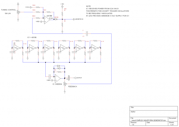
| ELEKTRICGASCHIEF wrote: | | Another way of making a VCO with the 40106 is to vary the supply voltage. The relationship is far from linear and is also inversely proportional, that is the output frequency falls as the supply voltage is increased. |
I wouldn't say that's a VCO, it's a method of power starving. However your circuit is very interesting, that feedback control looks like it would have a very interesting effect, you should have made a thread for it! I'd like to hear it in operation
The inverse relationship between frequency and input voltage is due to the hysteresis voltage of the 40106, the schmitt trigger trip points will vary for different supply voltages, getting further apart as the voltage increases.
_________________
As a mad scientist I am ruled by the dictum of science: "I could be wrong about this but lets find out"
Green Dungeon Alchemist Laboratories |
|
|
Back to top
|
|
|
|

 Forum index » DIY Hardware and Software » Lunettas - circuits inspired by Stanley Lunetta