| Author |
Message |
neandrewthal

Joined: May 11, 2007
Posts: 672
Location: Canada
|
 Posted: Thu Nov 13, 2008 2:17 am Post subject:
Dome filter Posted: Thu Nov 13, 2008 2:17 am Post subject:
Dome filter
Subject description: What exaclty does it do? |
  |
|
There is hardly anything written on the dome filter, but if I were to take a guess at what it does, I would say you insert a signal and it shifts it 90 degrees. IMO this would be incredibly useful, so therefore I must be wrong, since Ken's page says it is not a stand-alone project or of use to most people. So, is there any other use for it besides the basis of a frequency shifter? Also, does anyone know of a module that will perform the function I described?
_________________
" I went through quite a few trannies til I found one I liked" - Wild Zebra |
|
|
Back to top
|
|
 |
Luka

Joined: Jun 29, 2007
Posts: 1003
Location: Melb.
|
|
|
Back to top
|
|
|
yusynth

Joined: Nov 24, 2005
Posts: 1314
Location: France
|
| Posted: Thu Nov 13, 2008 3:22 am Post subject:
|
|
|
| Luka wrote: | sounds like what the mankato does
perhaps read more up on that design |
Not exactly the same, the dome filter is intended to be an allpass filter which provides with a 90° phase shift over all the frequency range, while the mankato provides a 90° phase shift at the cut-off frequency.
To answer the first question, yes the first application is that of frequency shifter. It may also be used as frequency doubler if you feed the two pase shifted outputs to the two inputs of a balanced modulator (MC1496 or other), since the phase shift is constant over a wide bandpass, all the partials are doubled in frequency.
Another application is to create a spacialization of a monophonic source : feed two outputs to separate inputs of a stereo mixer and set the pan pots to a different position and the monophonic sound will spread over a solid angle.
_________________
Yves |
|
|
Back to top
|
|
|
Luka
Joined: Jun 29, 2007
Posts: 1003
Location: Melb.
|
|
|
Back to top
|
|
|
yusynth
Joined: Nov 24, 2005
Posts: 1314
Location: France
|
| Posted: Thu Nov 13, 2008 4:53 am Post subject:
|
|
|
It is a phase shifter, but such a device is what is primarily called an all-pass filter.
_________________
Yves |
|
|
Back to top
|
|
|
neandrewthal
Joined: May 11, 2007
Posts: 672
Location: Canada
|
| Posted: Thu Nov 13, 2008 11:53 am Post subject:
|
|
|
| yusson wrote: | | Luka wrote: | sounds like what the mankato does
perhaps read more up on that design |
Not exactly the same, the dome filter is intended to be an allpass filter which provides with a 90° phase shift over all the frequency range, while the mankato provides a 90° phase shift at the cut-off frequency.
|
So, say you put in a sawtooth and shift it 90° over the whole frequency range. Does it still look like a sawtooth after?
I love the mankato, but it's such a nice filter as well, and only does sine waves. I've been looking at the ChaQuo too, but once again it's only sines and has no voltage control. What we need is a module that will turn any source into a quadrature oscillator 
_________________
" I went through quite a few trannies til I found one I liked" - Wild Zebra |
|
|
Back to top
|
|
|
yusynth
Joined: Nov 24, 2005
Posts: 1314
Location: France
|
| Posted: Thu Nov 13, 2008 12:38 pm Post subject:
|
|
|
| neandrewthal wrote: | | So, say you put in a sawtooth and shift it 90° over the whole frequency range. Does it still look like a sawtooth after? |
If your dome filter is perfect, yes, I think so.
_________________
Yves |
|
|
Back to top
|
|
|
neandrewthal
Joined: May 11, 2007
Posts: 672
Location: Canada
|
| Posted: Thu Nov 13, 2008 1:54 pm Post subject:
|
|
|
| yusson wrote: | | neandrewthal wrote: | | So, say you put in a sawtooth and shift it 90° over the whole frequency range. Does it still look like a sawtooth after? |
If your dome filter is perfect, yes, I think so. |
Hmm, well what do you mean by "perfect"? 0.1% resistors and such? I guess the slightest error would produce a nasty glitch in your waveform?
If the CGS dome filter can do this, then I can't understand why Ken basically labels it as useless 
_________________
" I went through quite a few trannies til I found one I liked" - Wild Zebra |
|
|
Back to top
|
|
|
blue hell
Site Admin

Joined: Apr 03, 2004
Posts: 24593
Location: The Netherlands, Enschede
Audio files: 309
G2 patch files: 320
|
| Posted: Thu Nov 13, 2008 2:01 pm Post subject:
|
|
|
I think a couple of things get mixed up here? As I understand things there are constant time delay filters and there are constant phase filters. And these are different things; a constant time delay would result in a linearly changing phase.
A constant time delay filter will pass arbitrary waveforms unchanged but delayed in time, this is used for phasers for instance. A constant phase filter, like the dome filter (why is it called a dome filter BTW?) used by Ken Stone (and also Jürgen Haible ), can be used for frequency shifters. These will not pass arbitrary waveforms with unchanged shape (but as the spectral content is not changed the filtered signal should still sound the same I think ...)
Some refs :
http://www.jhaible.heim.at/fs1a/fs1a.html
http://www.cgs.synth.net/modules/cgs45_domefilter.html
http://en.wikipedia.org/wiki/All-pass_filter
_________________
Jan
also .. could someone please turn down the thermostat a bit.
 |
|
|
Back to top
|
|
|
yusynth
Joined: Nov 24, 2005
Posts: 1314
Location: France
|
| Posted: Thu Nov 13, 2008 2:10 pm Post subject:
|
|
|
By perfect, I mean a 90° shift within 0.1% over a 30kHz bandpass (and this is difficult to achieve when you consider the tolerance of components). If not, some partial will not be in phase and this might change the output waveshape (though the harmonic amplitudes are maintained).
I think Ken meant that the dome filter on it's own is useless but that one has to experiment by combining it with other circuits to find some interesting applications. In other words this is not a "plug-in" board, it is a more demanding circuit.
_________________
Yves |
|
|
Back to top
|
|
|
certain2
Joined: Nov 21, 2008
Posts: 5
Location: yorkshire
|
| Posted: Tue Jun 30, 2009 11:54 am Post subject:
|
|
|
>>A constant phase filter, like the dome filter (why is it called a dome filter BTW?)
Robert B. Dome,
"Phase Shift System", Canadian Patent CA490405, 1953
You can get it from http://ep.espacenet.com/ Do a number search
or smart search on CA490405
He apparently worked for General Electric, Canada and had a
large number of patents on tube/valve audio/video circuits. |
|
|
Back to top
|
|
|
CJ Miller

Joined: Jan 07, 2007
Posts: 368
Location: 127.0.0.1
|
| Posted: Mon Jul 20, 2009 2:35 am Post subject:
values I used |
|
|
I finally got myself to brave stuffing my Dome boards... The formula for the recommended component values is screened onto the top, and I had already read about the circuit in Electronotes #83. Since I had the suggested capacitors I decided to fuss with resistor values, since I have more to choose from. It took me about four hours of going through resistors and measuring to get these close, so hopefully this might save somebody some time.
Stage cap resistance (used)
1 .47uF 62.6k (62.2k+330r)
2 .47uf 8.24k (8.25k)
3 .047uF 20.3k (12.1k+8.25k)
4 .0082uF 28.9k (27.4k+1.5k)
5 .0082uF 7.20k (6.81k+487r)
6 .0082uF 1.62k (820r+820r)
7 .47uF 18.0k (16.5k+1.5k)
8 .047uF 40.6k (39.2k+1.5k)
9 .0082uF 57.9k (49.9k+8.25k)
10 .0082uF 14.4k (14k+487r)
11 .0082uF 3.55k (2.21k+1.37k)
12 .0082uF 467r (180r+287r)
This was the easist to do with what i had on hand. It still took lots of measuring various combinations, sometimes even trying the same value from different manufacturers. Still I was able to get within a few hundreths for each value, many of them spot on.
As for what to do with these? I was thinking I might build something like the Electronotes frequency shifter, but unlike most people's leave it more openly modular so the subcircuits can be blocks to be patched. Why not have a high-frequency sine VCO, multipliers, and phase networks to play with? It'll be a while yet though, I am still building my basic setup. |
|
|
Back to top
|
|
|
zthee

Joined: Feb 20, 2008
Posts: 414
Location: Stockholm
|
| Posted: Mon Jul 20, 2009 3:58 am Post subject:
|
|
|
So let's say I build 2 of these boards.
I use one for the carrier and one for the signal. Then I use a balanced modulator, like the MC1496 and sum/multiply them together. And I got a Frequency shifter?
It sounds a little bit to straight forward.. So what's the catch?
Can I use anything else instead of the MC1496? I guess a normal ring modulator wouldn't do?
_________________
http://www.thehumancomparator.net/ |
|
|
Back to top
|
|
|
CJ Miller
Joined: Jan 07, 2007
Posts: 368
Location: 127.0.0.1
|
| Posted: Mon Jul 20, 2009 5:41 am Post subject:
|
|
|
| zthee wrote: | | It sounds a little bit to straight forward.. So what's the catch? |
The catch is that it's a fairly large, involved project. It probably requires lots of adjustment. As I understand it, first one uses a pair of multipliers in parallel on a fixed 20kHZ oscillator and a quadrature VCO. Then we'd process our signal of choice through a Dome filter. The VCO sine and Dome sine are routed through a multiplier, and their cosines are routed through another multiplier. The multipliers outputs are summed and passed through VCAs which use an envelope extracted from the input signal.
| zthee wrote: | | Can I use anything else instead of the MC1496? I guess a normal ring modulator wouldn't do? |
You could use MC1496, but a more precision multiplier would probably be far less noisy. It is already a drastic effect, and people say that too little linearity between it's input and output detracts from it's usefulness. If it gets too noisy, the output might not resemble the input any longer! The original called for AD533, but the newer AD633 will probably be fine.
Personally I think it might be fun to try non-standard settings. What if the phases aren't 90 degrees? What if the phases are changing? What if the quadrature VCO can do more complex waveshapes than sine? And yes, it is possible to use a second Dome filter instead of a VCO, but the result would be very complex. I don't know if I'd like the sound, but I want to hear these things.
I recommend Jurgen Haible's page on frequency shifting, where he explains his circuit. I am a noob and only beginning to understand this. |
|
|
Back to top
|
|
|
zthee
Joined: Feb 20, 2008
Posts: 414
Location: Stockholm
|
|
|
Back to top
|
|
|
angakok_thoth

Joined: Sep 02, 2016
Posts: 2
Location: Prague
|
| Posted: Fri Sep 02, 2016 7:02 pm Post subject:
|
|
|
| yusynth wrote: | | neandrewthal wrote: | | So, say you put in a sawtooth and shift it 90° over the whole frequency range. Does it still look like a sawtooth after? |
If your dome filter is perfect, yes, I think so. |
No it won't *look* like sawtooth, if we are talking about the shape of the wave (which will change) and not about it's harmonic content and sound (which will stay the same).
Even if the dome filter would do 90deg shift, it would not look as saw-wave anymore. Imagine the saw-wave decomposed into its sine-wave components - each component has a different wavelength, so for each of them the 90degrees shift means a delay by different time... When you add them up back together, the shape is different. (i believe it's like that for all waves other than single pure single sine-wave without any harmonics and for any amount of phaseshifts except for 0deg and multiples of 360deg)
...and this dome filter doesn't do 90deg phase shift to the input anyway. What this dome filter does, is creating two outputs with 90deg phase shift between them. So it is not 90deg phase shift between input and output, it is between output1 and output2. And neither of them will look like saw. But will sound the same. |
|
|
Back to top
|
|
|
angakok_thoth
Joined: Sep 02, 2016
Posts: 2
Location: Prague
|
|
|
Back to top
|
|
|
L´Andratté

Joined: Sep 23, 2012
Posts: 153
Location: Hamburg, Germany
Audio files: 5
|
| Posted: Wed Dec 07, 2016 7:25 am Post subject:
|
|
|
| Thanks for the information, angakok_toth! |
|
|
Back to top
|
|
|
soundworker
Joined: May 31, 2013
Posts: 21
Location: Germany
Audio files: 1
|
| Posted: Wed Jan 23, 2019 9:46 am Post subject:
Dome-Filter and Multiplier pair .... |
|
|
Just finished my FS project.
A 12 stage Dome Filter and two AD 633 as RMO form a part of this FS design.
For work you need a quadrature VCO. Doepfer A110-4 or so work perfect.
Look at klangbaukoeln for more information. |
|
|
Back to top
|
|
|
mediatechnology

Joined: May 10, 2006
Posts: 80
Location: Oak Cliff, Texas USA
|
Posted: Sat Aug 14, 2021 12:52 pm Post subject:
Studer 90° Dome Filter
Subject description: A modern interpretation of the Studer Dome filter with improved alignment |
|
|
Hi all.
I wanted to share with you some work I've been doing with the Studer 90° Dome filter over at the Pro Audio Design Forum.
https://proaudiodesignforum.com/forum/php/viewtopic.php?f=6&t=1055
My interest in the Studer Dome filter is multi-fold: One is to make better mono fold down of early stereo recordings. The second is to make better mono fold down during tracking problematic synth patches. A third is to improve mono "in-store" background music and AM broadcast.
AM broadcast is apparently what drove Studer, LAWO and others to originally make Dome filter boards. If I were to make boards to offer I doubt I'd sell many but this is one gizmo I want in my toolbox for the very few times I'd need it. I'd be laying out a board mostly for me. Poor mono fold-down of synth patches is a frequent complaint - some people might want it for that.
What's useful about the Dome filter is the near-constant 90° phase differential. When Left and Right are summed conventionally the L-R "Side" information is completely cancelled. The mono sum increases in level by usually 4-6 dB depending on correlation.
The 90° Dome filter sums L+R to +3 dB. The out-of-polarity L-R Side information also sums to +3dB instead of -∞.
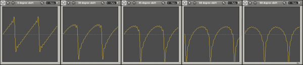
I demonstrate that with tone:
I used Cool Edit to lay down 440 Hz tone at -6 dBFS in mono.
I created a second file using 220 Hz tone, also at -6 dBFS and feeding both channels, but with the relative polarity inverted in the right channel.
I then summed them.
The resulting file was processed by the Quadrature summing filter.
The first section is the unaltered stereo file followed by the I+Q sum, the L+R sum, etc.
The L+R sum can be easily identified - it's missing the 220 Hz tone due to phase cancellation.
Disappearing "out-of-polarity" 220 Hz tone: https://proaudiodesignforum.com/content/Quadrature_Summing_Filter_Two_Tone_Stereo_IQ_LR.mp3
In this post I provide two samples of the Beatles "Paperback Writer"
https://proaudiodesignforum.com/forum/php/viewtopic.php?f=6&t=1055&start=20#p16555
One is conventional L+R the other the 90° "I+Q" sum. Let me know which sounds best to you with a guess as to which one is the 90° "I+Q" sum.
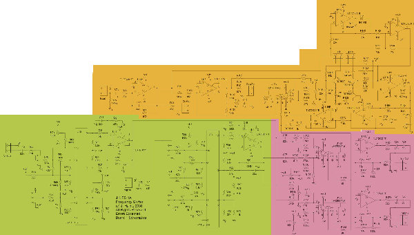
Here's the schematic of my interpretation of the Studer filter with improved "Weaver" alignment:

The Studer 90° Dome Filter Mono Recombiner with Weaver Alignments


_________________
Visit https://ka-electronics.com/shop/ |
|
|
Back to top
|
|
|
mediatechnology
Joined: May 10, 2006
Posts: 80
Location: Oak Cliff, Texas USA
|
|
|
Back to top
|
|
|
|

 Forum index » DIY Hardware and Software » Ken Stone designs - CGS