guitarfool

Joined: Feb 26, 2007
Posts: 161
Location: Maryland
Audio files: 8
|
 Posted: Fri Dec 26, 2008 5:43 pm Post subject:
CGS-45 Dome Filter Posted: Fri Dec 26, 2008 5:43 pm Post subject:
CGS-45 Dome Filter |
  |
|
I've started playing around with the CGS45 Dome Filter PCBs, and found one small error. The 10k input resistor is supposed to connect to the "+" input of the TL071. Instead, it's connected to the "-" input (the output and negative feedback trace) and the "+" input is unconnected. I de-soldered the 10k resistor and used a jumper wire to the "+" input. See pic below.
Other than that, I believe its okay. And it is the same circuit as Jurgen Haible's (as used in the Frequency Shifter), so anyone who wants to build one can just follow his instructions for the FS1 here: http://www.jhaible.heim.at/fs1a/fs1a.html The schematic is the middle section of board 2. He also has a nice excel spreadsheet for calculating the resistor values. The silkscreen on Ken's card gives the time constants ("t") in milliseconds, whereas Jurgen uses microseconds.
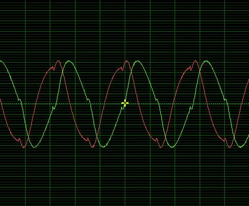
Here's a couple of scope shots of the CGS45 in action. The results are pretty constant across the audio range. The sine looks pretty good, the triangle is a bit sketchy. Square and sawtooth waves are even more so. I haven't checked the output of the dome filter in my FS-1, but I'm sure its the same. I used polyester caps for the 2 biggest caps: the 100nF C1 (29400 uSec = 29.4 mSec) and the 22nF C7 (8470 uSec = 8.47 mSec). I couldn't source polystyrene caps that big. I ordered some polypropylene caps for these 2 values. When I get them I'll see if it makes a difference. This is only a 6 stage version - Jurgen's 12 stage version may give better results. Seems to be good enough for a frequency shifter though 
| Description: |
|
| Filesize: |
63.25 KB |
| Viewed: |
5265 Time(s) |

|
| Description: |
|
| Filesize: |
60.91 KB |
| Viewed: |
5266 Time(s) |
|
| Description: |
|
| Filesize: |
147.36 KB |
| Viewed: |
447 Time(s) |
| This image has been reduced to fit the page. Click on it to enlarge. |

|
|
|
otherunicorn

Joined: May 11, 2008
Posts: 136
Location: Australia
|
| Posted: Sat Jan 03, 2009 12:01 am Post subject:
|
|
|
That messed up input is a known fault on the first run of the PCBs. Phase shifting of complex wave shapes such as square waves does mess up how they appear on the CRO, but as our hearing is phase insensitive, it does not matter.
_________________
http://www.cgs.synth.net/ |
|

 Forum index » DIY Hardware and Software » Ken Stone designs - CGS
