| Author |
Message |
DrKoester
Joined: Mar 17, 2009
Posts: 18
Location: Highland Park, NJ
|
 Posted: Wed Apr 22, 2009 7:26 pm Post subject:
Powering the sub-commander (and some other ?'s) Posted: Wed Apr 22, 2009 7:26 pm Post subject:
Powering the sub-commander (and some other ?'s) |
  |
|
Before I embark on the MFOS sub-commander guitar synth project I have some questions, mainly with regard to power. Before I get going, I'm an electronics noob. I am a guitarist and a pedal-junkie. I have modified popular Boss stompboxes and built three units from kits (solder-by-number). So while I'm capable of following instructions, much of the technical end is a blur. But I'm willing to learn!
So, power. Is it worth it to build Ray's bipolar power supply? Or a PAiA kit like this: http://www.paia.com/proddetail.asp?prod=K83&cat=50? If I build this power supply, does it need to be isolated from the rest of the circuit? Can it go in the same enclosure?
Or, should I use batteries? If so, how are they wired? Any directions on how to do this?
So this is just the beginning...I have a lot to learn but thanks in advance for your input.
-Tom |
|
|
Back to top
|
|
 |
toybox

Joined: Aug 03, 2005
Posts: 176
Location: chicago/peru,illinois usa
|
|
|
Back to top
|
|
|
DrKoester
Joined: Mar 17, 2009
Posts: 18
Location: Highland Park, NJ
|
| Posted: Sun Apr 26, 2009 7:03 am Post subject:
|
|
|
Great thanks. I will probably make rays power supply and mount it in the same large enclosure.
How about wiring in true bypass stompswitch? If you had a handy pic of that too that would be excellent! |
|
|
Back to top
|
|
|
DrKoester
Joined: Mar 17, 2009
Posts: 18
Location: Highland Park, NJ
|
| Posted: Mon Apr 27, 2009 4:52 pm Post subject:
|
|
|
additional n00b question: Audio or linear taper pots? The parts list calls for 4 of the pots to be audio. I figure the remaining pots should be linear since they are unspecified. Yes?
Thanks![/url] |
|
|
Back to top
|
|
|
Wizard Mike
Joined: Jan 26, 2009
Posts: 52
Location: Charlotte
|
| Posted: Mon Apr 27, 2009 8:22 pm Post subject:
|
|
|
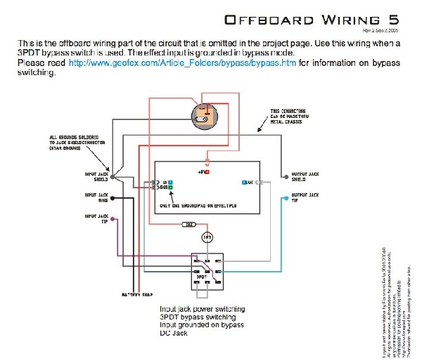
tonepad.com has some really useful articles, schematics, board layouts and wiring instructions. Here are some options for installing the bypass switch on your sub commander:
http://www.tonepad.com/getFile.asp?id=76
I recommend breezing through their site and checking out some of their other plans. It has helped me out tons on my guitar effects projects. |
|
|
Back to top
|
|
|
DrKoester
Joined: Mar 17, 2009
Posts: 18
Location: Highland Park, NJ
|
|
|
Back to top
|
|
|
Wizard Mike
Joined: Jan 26, 2009
Posts: 52
Location: Charlotte
|
|
|
Back to top
|
|
|
Wizard Mike
Joined: Jan 26, 2009
Posts: 52
Location: Charlotte
|
| Posted: Sat May 02, 2009 7:52 pm Post subject:
|
|
|
... at least that looks like it should go  |
|
|
Back to top
|
|
|
goodrevdoc

Joined: Sep 11, 2006
Posts: 288
Location: Philadelphia, PA
Audio files: 1
|
| Posted: Sat May 02, 2009 11:43 pm Post subject:
|
|
|
Here's a less known power hookup tip. You can use one of these jacks:
http://www.smallbearelec.com/Detail.bok?no=724
wired as the input jack and it will do the normal stompbox switched off when no plug inserted thing. the wiring is posted somewhere on the net. I'll see if i can find it. Ray's designs are wonderfully current miserly so the two battery solution seems good here, especially for less experienced builders. Also, this eliminates the need for a line cord if in fact you plan to use this as a stompbox. This little jack it should be noted, also works wonders as a soundlab output jack, eliminating the need for an on off switch...
-justin |
|
|
Back to top
|
|
|
goodrevdoc
Joined: Sep 11, 2006
Posts: 288
Location: Philadelphia, PA
Audio files: 1
|
| Posted: Sat May 02, 2009 11:57 pm Post subject:
|
|
|
Here is the data sheet for that jack. Its not too hard to figure out how to wire it, but i'll still try to find the diagram for info purposes...
-justin |
|
|
Back to top
|
|
|
DrKoester
Joined: Mar 17, 2009
Posts: 18
Location: Highland Park, NJ
|
| Posted: Sun May 03, 2009 5:18 pm Post subject:
|
|
|
| Thanks once again. The tonepad bipolar design only provides 9V though, correct? Any chip other than the MAX1044 that'll give 12V? |
|
|
Back to top
|
|
|
Wizard Mike
Joined: Jan 26, 2009
Posts: 52
Location: Charlotte
|
| Posted: Sun May 03, 2009 8:30 pm Post subject:
|
|
|
| I would still go with Ray Wilson's power supply. After looking at the diagrams and some stuff I have laying around you can get a cheepo power jack like the one illustrated in the previous diagrams and just use one of the positive lugs on the back to lead into the power supply. Both the sub commander and the power supply can go into one enclosure, but I would recommend using an entirely separate enclosure for the power supply. That way you can power other +\- 12 units in the future (MFOS Sound Lab hint hint) along with the sub commander. Think of it as a DC Brick or like a Voodoo Lab Pedal Power 2 except you'll have a 12v power supply. Then, after all of that, hook up your bypass switch. I usually buy from small bear. Use the tonepad site as reference and also look at some other sites like http://www.commonsound.com/kits/doku.php or http://www.buildyourownclone.com/index1.html and see how they did it. If I think to draw anything out I'll put it up here. I too am more of a guitar/gear whore so I know exactly where you are coming from! |
|
|
Back to top
|
|
|
Wizard Mike
Joined: Jan 26, 2009
Posts: 52
Location: Charlotte
|
|
|
Back to top
|
|
|
Wizard Mike
Joined: Jan 26, 2009
Posts: 52
Location: Charlotte
|
|
|
Back to top
|
|
|
DrKoester
Joined: Mar 17, 2009
Posts: 18
Location: Highland Park, NJ
|
| Posted: Mon May 04, 2009 2:15 pm Post subject:
|
|
|
you rock, Wizard. thanks!
I've been perusing BYOC a whole bunch. Tonepad, Geofex, and DIYstompboxes are all great too. I have a lot to learn here...still haven't purchased any components or PCBs because I want to get everything worked out first. Pretty close here though...been hacking out a panel design and found these nice enclosures http://www.action-electronics.com/lmkb.htm
Do you know what pot types to use? Ray lists 4 audio taper pots and 14 others that are not specified as audio or linear so I'm assuming linear. |
|
|
Back to top
|
|
|
Wizard Mike
Joined: Jan 26, 2009
Posts: 52
Location: Charlotte
|
| Posted: Mon May 04, 2009 10:36 pm Post subject:
|
|
|
| I've been looking around the forum and MFOS and can't find any clarification on the pot types, but I too would assume they are lin pots. They seem to be pretty common for controlling all the fun filters and what-not. You could send a message to one of the people who have completed it? They may have some better insight than I. |
|
|
Back to top
|
|
|
DrKoester
Joined: Mar 17, 2009
Posts: 18
Location: Highland Park, NJ
|
| Posted: Sat May 23, 2009 12:42 pm Post subject:
|
|
|
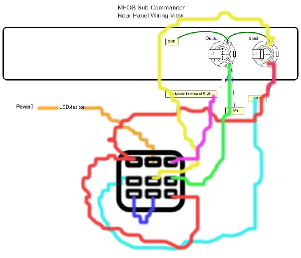
Alright, board is all done, pots are mounted on an old novelty road sign ready to test and now i'm wiring...
So my question is this, where does GTA2 get wired to on the panel? Looking at the schem and wiring diagram, I assume it would go to lug 2 (middle) of S3 but it isn't shown as such. |
|
|
Back to top
|
|
|
DrKoester
Joined: Mar 17, 2009
Posts: 18
Location: Highland Park, NJ
|
| Posted: Sat May 23, 2009 12:46 pm Post subject:
|
|
|
| Same question for RDA2....do I just wire the middle lugs of S2 and S4 together and S1 and S3 and then wire nothing to the GTA2 and RDA2 positions on the board? |
|
|
Back to top
|
|
|
Wizard Mike
Joined: Jan 26, 2009
Posts: 52
Location: Charlotte
|
| Posted: Sun May 24, 2009 6:41 am Post subject:
|
|
|
| I would recommend just wiring it all as shown on the site and leave out anything that isn't illustrated, in the schem, or described in the circuit description. Put it all together and see what happens. It is very plausible that those are areas on the board that you could add mods (I've seen this done on other designers circuit boards) and aren't entirely necessary for circuit operation. That being said, if you wire it all together and nothing seems to work and it appears that these points are necessary, then it will show that I have no idea what I'm talking about |
|
|
Back to top
|
|
|
DrKoester
Joined: Mar 17, 2009
Posts: 18
Location: Highland Park, NJ
|
| Posted: Sun May 24, 2009 8:56 am Post subject:
|
|
|
| Thanks, that's what i ended up doing. Still have about 1/4 of the wiring left and then we see what happens... |
|
|
Back to top
|
|
|
DrKoester
Joined: Mar 17, 2009
Posts: 18
Location: Highland Park, NJ
|
| Posted: Sun Jul 26, 2009 5:43 pm Post subject:
|
|
|
| So my project is in the trouble-shooting phase at this point and I'm beginning to wonder if my power supply is working correctly. The voltages are about +13.5 and -10.25. Any thoughts? The only difference in my build and the build instructions is I don't have the heatsinks of my regulators attached to the PCB with a screw because screws weren't supplied and I didn't have a fit. Is this essential to the build at all? |
|
|
Back to top
|
|
|
|

 Forum index » DIY Hardware and Software » MusicFromOuterSpace.com designs by Ray Wilson