| Author |
Message |
Dez
Joined: May 05, 2008
Posts: 8
Location: Brooklyn
|
 Posted: Sat Jun 13, 2009 2:28 pm Post subject: Posted: Sat Jun 13, 2009 2:28 pm Post subject:
 CGS48 VCO Help CGS48 VCO Help |
  |
|
Hi all,
I come seeking help from the great electromusic collective mind. Maybe some of the issues I'm having will ring a bell. I'm pretty noob-y so it may be / probably is something simple.
So the first time I fired up my CGS48 it didn't exactly sound like what I expected (massive understatement  ) I went through the typical debugging checklist. Checked my parts/wiring, solder bridges, shorts, jumpers, etc. Triple checked. No results. ) I went through the typical debugging checklist. Checked my parts/wiring, solder bridges, shorts, jumpers, etc. Triple checked. No results.
My next step was to disconnect all pots and jacks in an attempt to isolate the problem. Still no results.
So here's whats happening now:
The saw output is giving me a strange sound that doesn't really resemble anything close to a saw ( http://dezmm.com/pickup/CGS48/Saw.mp3 ), the sine output looks more like something between a square and a saw ( http://dezmm.com/pickup/CGS48/Sine.mp3 ), and the square is just weird (although it does actually resemble a square after its been on for a few minutes: http://dezmm.com/pickup/CGS48/Square.mp3 ).
So if you give these a listen, you'll notice that there is also some weird modulation going on, that I can't account for. The wave-form is constantly changing.
The other big problem is that the tune doesn't seem to be working at all. I have a 100k pot wired between VE- and VE+, with the wiper attached to tune, but nothing happens. Actually there is some change in the sound, but the tune doesn't change.
My noob-ish sense is telling me that a wonky/dead TL072 could be the culprit. I actually removed the 1st one on top (IC2 i think) and it changed nothing. Same weird sounds.
Thanks in advance. This is my last attempt to save this project before I throw in the towel. |
|
|
Back to top
|
|
 |
RF

Joined: Mar 23, 2007
Posts: 1502
Location: Northern Minnesota, USA
Audio files: 28
|
| Posted: Sat Jun 13, 2009 4:01 pm Post subject:
|
|
|
Hi Dez
What kind of power supply are you using?
bruce
_________________
www.sdiy.org/rfeng
"I want to make these sounds that go wooo-wooo-ah-woo-woo.”
(Herb Deutsch to Bob Moog ~1963) |
|
|
Back to top
|
|
|
Dez
Joined: May 05, 2008
Posts: 8
Location: Brooklyn
|
| Posted: Sat Jun 13, 2009 4:21 pm Post subject:
|
|
|
I'm using my desktop power supply set to 15v. I tied 12v just to see what would happen. Pretty much the same result.
thanks |
|
|
Back to top
|
|
|
andrewF

Joined: Dec 29, 2006
Posts: 1176
Location: australia
Audio files: 4
|
| Posted: Sat Jun 13, 2009 6:57 pm Post subject:
|
|
|
Hi Dez
the VCO can be a challenge, it is not the easiest circuit to build in the CGS range. Nevertheless they do work!
If you built it for a +/-15V supply it probably won't work on +/-12V, as the input for the LM311 comparator will be wrong.
So keep it at +/-15V.
The TL072 at the top of the schematic is part of the CV processor sub-circuit and not part of the VCO core. So it can be ignored for now, leave the chip out until the core is working.
very common problems with building the VCO stem from the FET, some types don't work well, or are installed incorrectly. What FET do you have?
other problems are missing links/jumpers, there are some very small ones on this PCB. A common check for missing components is to hold the PCB up to a light and look for 'stars' where the light is shining thru the holes.
Usually, so long as chips don't get hot and fried, chips are the last things to worry about, there are many things to go wrong before chips poop themselves.
The sine output needs setting up with the trimpots and won't be pretty until that is done
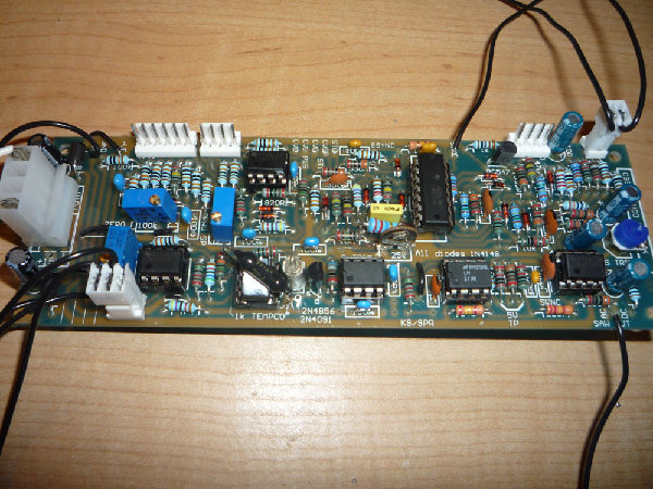
So, let us know the FET type, check its orientation, look for stars and, if you like, take some close-up photos of the board and post them.
Best to view debugging as a free lesson in how the circuit works.
Have fun! |
|
|
Back to top
|
|
|
hobgob_inc
Joined: Jun 09, 2009
Posts: 46
Location: Australia
|
| Posted: Sun Jun 14, 2009 12:12 am Post subject:
|
|
|
Hey Andrewf,
On a similar topic of VCO help, could you tell me how many volts the sine should be measuring? I think I'm getting the problem of higher frequencies being reduced in level
Also if the sine wave is not sitting on 0v, would this be due to incorrect offset of the saw tooth?
Thanks, Luke |
|
|
Back to top
|
|
|
andrewF
Joined: Dec 29, 2006
Posts: 1176
Location: australia
Audio files: 4
|
| Posted: Sun Jun 14, 2009 1:06 am Post subject:
|
|
|
Hi Luke
 to electro-music! to electro-music!
My TSO and ATSO outputs give about 4V p-p
Sine output is 3V p-p with 2V offset. As in it oscillates between 0.5V and 3.5V.
you should be able to adjust these p-p levels with the 22k trimpot shown in the bottom left corner of the schematic.
I seem to remember reading somewhere, at higher frequencies the 2n2 cap (under the FET) doesn't have time to charge up fully, hence the output waveform is smaller.
Are you seeing sawtooth offset? mine run from 0-4V. i don't think this would contribute to the DC offeset of the sine output, as the 4u7 caps after the 22k trimpot remove any DC from the signal.
Ken's article notes "Don't expect a perfect waveform - it will most likely have a substancial glitch in it at its best setting. Remember - this sine output is simply there to make use of a spare part of the LM3900 - it is not a key feature of the design. "
Sounds like you have the circuit running fairly well
andrew |
|
|
Back to top
|
|
|
hobgob_inc
Joined: Jun 09, 2009
Posts: 46
Location: Australia
|
| Posted: Sun Jun 14, 2009 1:16 am Post subject:
|
|
|
Thanks for the welcome Andrew. I have been reading the forums for so many months now ( much knowledge and wisdom has come from you i must say, and others) so i thought it was about time i joined.
Good news about the VCO stuff that all sounds fairly on par with how my pair are running. Thanks for the verification!
thanks again, Luke |
|
|
Back to top
|
|
|
Dez
Joined: May 05, 2008
Posts: 8
Location: Brooklyn
|
|
|
Back to top
|
|
|
hobgob_inc
Joined: Jun 09, 2009
Posts: 46
Location: Australia
|
| Posted: Sun Jun 14, 2009 6:11 pm Post subject:
|
|
|
From looking at that picture it appears you have no zero volts going to the circuit?? This could be a problem
Probably the most common problem i have when testing a new circuit is that the power rails are not correctly reaching the circuit....Just a thought
Luke |
|
|
Back to top
|
|
|
Rykhaard
Joined: Sep 02, 2007
Posts: 1290
Location: Canada
|
| Posted: Sun Jun 14, 2009 7:30 pm Post subject:
|
|
|
| hobgob_inc wrote: | From looking at that picture it appears you have no zero volts going to the circuit?? This could be a problem
Probably the most common problem i have when testing a new circuit is that the power rails are not correctly reaching the circuit....Just a thought
Luke |
I agree there. Looking at the power input 0.156" connector, there're only +15 and -15 wires coming into the unit. Is the main Ground for the PCB hooked up to your main power supply?
Another observation: there're temperature related resistors, all over the place in this PCB. ??? (The 6 banded ones. Last colour ring on these - it's colour stands for the % of difference the resistor has, as per the surrounding temperature, if I recall correctly.
I wonder - if this resistor type (instead of 1% resistors) could have any factor in this as well? (Anyone - please correct me if I'm wrong.) |
|
|
Back to top
|
|
|
|

 Forum index » DIY Hardware and Software » Ken Stone designs - CGS