| Author |
Message |
Scott Stites
Janitor


Joined: Dec 23, 2005
Posts: 4127
Location: Mount Hope, KS USA
Audio files: 96
|
 Posted: Tue Dec 07, 2010 8:50 am Post subject: Posted: Tue Dec 07, 2010 8:50 am Post subject:
|
  |
|
Cool! That is an awesome build, too. I've got mine in a rack mount, but I'd like to put it into a portable case.
_________________
My Site |
|
|
Back to top
|
|
 |
numbernone
Joined: Aug 16, 2006
Posts: 477
Location: new york city
|
| Posted: Tue Dec 07, 2010 10:10 am Post subject:
|
|
|
OK, calibration time has come, and it appears I will have some questions.
Firstly, I am using the first version of the build documentation, is there an updated version?
Step 1. Easy, no sweat.
Step 2. I might not be understanding here. Beginning with a .008v reading and no gate LED lit, I cannot seem to get the LED to light nor the jump towards rail voltage IF I am pressing the ribbon. No amount of adjusting seems to get there while pressing down. However when I release, the voltage rises and the LED lights and stays that way. Without pressure I can find the trip point easily. Checking the upper part of the ribbon seems moot as the lowest part is not behaving properly.
If I am to understand correctly, the gate LED should light only while pressure is applied and NOT stay lit after(this would make sense but ...)
Step 3. I skipped to 3 just to see what its all about... VR2 adjustment to -4.75v no problem. Now the adjustment of VR3 will not go into positive voltage, it winds down to 0.00v but no positive gain no matter how many turns. I know VR2/3 are to have some interaction, I can fond no way to get a positive voltage from VR3.
I will leave it there for now. hopefully someone can sort me out.
thanks. |
|
|
Back to top
|
|
|
Scott Stites
Janitor
Joined: Dec 23, 2005
Posts: 4127
Location: Mount Hope, KS USA
Audio files: 96
|
| Posted: Tue Dec 07, 2010 3:43 pm Post subject:
|
|
|
We should probably check to see why problem 1 exists first.
The LED and gate signals are ultimately derived from a comparator determining if voltage is present on the ribbon input.
1. First of all, let's see if the ribbon voltage is correct. If there is no pressure on the ribbon, pin 10 of U13 should be 0V or so. Once you press on the ribbon, that voltage will jump up. The lower you are on the ribbon, the lower that voltage will be.
2. If you get the correct voltage response at pin 10 of U13, make sure that pin 8 of U13 follows that voltage faithfully.
3. If step 2 is OK, make sure the voltage is making it to R47, which connects to pin 2 of the comparator U12 (this would be the end of R47 facing the edge of the board - sorry, didn't mark that).
4. If the voltage is making it to R47, then Pin 1 of U12 should go low when the voltage on R47 exceeds the voltage as set by VR1. When you adjust VR1, you are setting the trip point for the lowest voltage produced by the ribbon.
5. If that is happening, check TP7 to ensure that it is actually tripping high when Pin 1 of U12 trips low. If it is not, check the comparator reference voltage (produced by R54 and R22) on pin 5 of U12. This should be around 1.4 or slightly less (assuming a 15V supply is being used).
| Description: |
|

Download (listen) |
| Filename: |
Appendage_Comparator.pdf |
| Filesize: |
36.8 KB |
| Downloaded: |
1376 Time(s) |
_________________
My Site |
|
|
Back to top
|
|
|
numbernone
Joined: Aug 16, 2006
Posts: 477
Location: new york city
|
| Posted: Tue Dec 07, 2010 4:54 pm Post subject:
|
|
|
Hmmm... Pin 10 is 7.97 v+ with no pressure. Dips to 4.5v+ with pressure at low point, back to 7.97 highest point. Pin 8 is following right along.
ADDENDUM:
Tiny tiny teensy short on 2 of the last 3 wires I soldered for the softpot...DUH
getting better now I hope. Be back for more later I am sure. |
|
|
Back to top
|
|
|
numbernone
Joined: Aug 16, 2006
Posts: 477
Location: new york city
|
| Posted: Tue Dec 07, 2010 7:27 pm Post subject:
|
|
|
90% there now. TFS is adjusting funny but getting useful results nonetheless. Will deal with them later.
Can already tell this will be amazing. |
|
|
Back to top
|
|
|
Scott Stites
Janitor
Joined: Dec 23, 2005
Posts: 4127
Location: Mount Hope, KS USA
Audio files: 96
|
| Posted: Tue Dec 07, 2010 8:01 pm Post subject:
|
|
|
Wow, cool. I saw the voltage readings on the ribbon, but I couldn't reply because I had to go to my son's Christmas concert. What did you figure out was the deal?
I can dig the cal being a drag - it can be a pain in the ass. I helped Scot Solida with his, and, after over a year since I calibrated mine, it kicked my ass, and I was following my own directions.... 
_________________
My Site |
|
|
Back to top
|
|
|
numbernone
Joined: Aug 16, 2006
Posts: 477
Location: new york city
|
| Posted: Tue Dec 07, 2010 9:25 pm Post subject:
|
|
|
Shorted pads on the board for the ribbon.
EVerything is pretty much sorted, except for the TFS, both modes. Unable to trim the double pressure part. Giving me 13.86v for the widest spread. Trimmer doesnt move it either direction.
Got it closed back up for the night, too much fun to fiddle with anymore without making space sounds.
You have made a wonderful thing Scott. |
|
|
Back to top
|
|
|
Scot Solida
Joined: Oct 24, 2009
Posts: 100
Location: Hutchinson Kansas
|
| Posted: Wed Dec 08, 2010 5:27 am Post subject:
|
|
|
| Scott Stites wrote: |
I can dig the cal being a drag - it can be a pain in the ass. I helped Scot Solida with his, and, after over a year since I calibrated mine, it kicked my ass, and I was following my own directions.... |
And I will be eternally grateful that you took that ass-kicking on my behalf.
Though in all seriousness, the thing is solid as a rock now. After having received his whoopin', Scott wrestled the wee beastie into submission and it has been performing like a champ since.
There oughta be some kinda sainthood given to a man who'll take on a calibration for another DIY'er! |
|
|
Back to top
|
|
|
Scott Stites
Janitor
Joined: Dec 23, 2005
Posts: 4127
Location: Mount Hope, KS USA
Audio files: 96
|
| Posted: Wed Dec 08, 2010 5:45 pm Post subject:
|
|
|
Well, thanks guys. I suppose it would be a toss-up between tar-and-feathers or sainthood, depending on which side of the cal you're on.
Seriously, though, the same offer as I've made on the Klee stands to any builder who hits a point that seems insurmountable - send it to my place and I'll get it working one way or the other. For wife-related reasons, the only thing I require would be return postage.
I hope you all enjoy your Appendages as much as I enjoy mine.
_________________
My Site |
|
|
Back to top
|
|
|
Scot Solida
Joined: Oct 24, 2009
Posts: 100
Location: Hutchinson Kansas
|
| Posted: Wed Dec 08, 2010 6:03 pm Post subject:
|
|
|
| Scott Stites wrote: |
I hope you all enjoy your Appendages as much as I enjoy mine. |
I am sure I do... It has given new life to my modular and has become one of those modules that is in nearly every patch patch I make.
Mind you, I may never be able to wring the incredible stuff out of it that I heard you do with the thing! |
|
|
Back to top
|
|
|
Scott Stites
Janitor
Joined: Dec 23, 2005
Posts: 4127
Location: Mount Hope, KS USA
Audio files: 96
|
| Posted: Fri Dec 10, 2010 8:42 pm Post subject:
|
|
|
Nothing I've done kicks it out like that last link you sent, me, Scot!
As for my offer to help out on any Appendage probs, one should reach me at scott(dot)stites at birthofasynth dot com.
You can see my email less cryptically spelled out at the bottom of my home page here:
www.birthofasynth.com
I'll get the message.
_________________
My Site |
|
|
Back to top
|
|
|
Photon

Joined: Mar 22, 2005
Posts: 363
Location: Boston
Audio files: 1
|
|
|
Back to top
|
|
|
Scott Stites
Janitor
Joined: Dec 23, 2005
Posts: 4127
Location: Mount Hope, KS USA
Audio files: 96
|
| Posted: Thu Feb 24, 2011 5:33 pm Post subject:
|
|
|
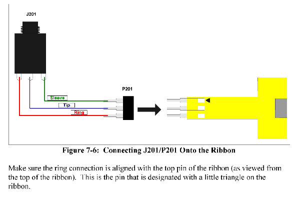
Yipes!
I believe the illustration is correct. The text is not....
Thanks, Photon!
_________________
My Site |
|
|
Back to top
|
|
|
philpeery
Joined: Nov 08, 2006
Posts: 137
Location: new jersey, usa
|
| Posted: Thu Jul 07, 2011 6:02 pm Post subject:
the BIG spoftpot... |
|
|
Hey Everyone!
I am getting ready (finally) to build my appendage (hmmmm...)! I have the 500mm spoftpot that I bought originally when I got the PCB, but my buddy just GAVE me a 1000mm softpot that they got when cleaning out an electronics lab that was shutdown where he works. Are there any issues or mods that need to be made to use the 1000mm? It would be WAY cool to be able to use it!
Best Regards,
Phil |
|
|
Back to top
|
|
|
State Machine
Janitor

Joined: Apr 17, 2006
Posts: 2810
Location: New York
Audio files: 24
|
| Posted: Sun Jul 10, 2011 8:03 am Post subject:
|
|
|
Hi Phil
| Quote: |
I am getting ready (finally) to build my appendage (hmmmm...)! I have the 500mm spoftpot that I bought originally when I got the PCB, but my buddy just GAVE me a 1000mm softpot that they got when cleaning out an electronics lab that was shutdown where he works. Are there any issues or mods that need to be made to use the 1000mm? It would be WAY cool to be able to use it |
No modifications will be required. The 500 mm and 1000 mm softpots are both 20K. Just jumper the positions at JP1, pins 2 to 3 as you would for a 500 mm SP.
Bottom line, your in luck man !! Enjoy.
Just as a rule of thumb, any softpot >300mm are all 20K.
Bill |
|
|
Back to top
|
|
|
philpeery
Joined: Nov 08, 2006
Posts: 137
Location: new jersey, usa
|
| Posted: Sun Jul 10, 2011 1:28 pm Post subject:
|
|
|
Hey Bill!
Thanks for the info on the softpot! I have started loading resistors on my boards (figured I'd do both at the same time), let the fun begin!
I will post pics of my finsihed appedages (careful, now!) when they are done!
Regards,
Phil |
|
|
Back to top
|
|
|
Scot Solida
Joined: Oct 24, 2009
Posts: 100
Location: Hutchinson Kansas
|
| Posted: Sun Jul 10, 2011 1:38 pm Post subject:
|
|
|
| I'll be bringing and playing the Appendage to the E-M festival in Kansas City in two weeks. The Appendage is awesome. |
|
|
Back to top
|
|
|
marvkaye
Joined: Mar 14, 2011
Posts: 225
Location: Fla
|
| Posted: Wed Jul 13, 2011 4:25 pm Post subject:
|
|
|
| Scot Solida wrote: | | I'll be bringing and playing the Appendage to the E-M festival in Kansas City in two weeks. The Appendage is awesome. |
I wish I could make it to KC to see and hear yours, as I really like your dotcom panel, not to mention your Walking Stick enclosure... nice job!! I'm in on the next run of PCBs and am gathering parts, info, thoughts... anything that will help with completing my own Appendage.
That being said, and now that you've got some actual Appendage time under your belt (is there a double entendre stuck in there?? this project seems to bring that out in people), I'm wondering if you're happy with your implementation and am curious if there's anything you would do differently. Also, any chance you'd be willing to share a full size PDF of your panel, or at least a larger photo that would make seeing everything a bit easier? And where'd you get the panel itself??? Sorry for all the questions, but this is a big project and there's a ton more where these came from. 
__________-
<Marv> |
|
|
Back to top
|
|
|
marvkaye
Joined: Mar 14, 2011
Posts: 225
Location: Fla
|
| Posted: Wed Jul 13, 2011 5:16 pm Post subject:
|
|
|
While I'm here asking questions, here are a couple for you, Bill.... is there a thread around where you describe your build a bit? I'm curious about how you implemented the CV/Trigger-to-MIDI section of your panel. It's very impressive and I'd really like to learn more about it. I'm also curious about the panel itself... did you have it done by FPE, do it yourself, or what? It's really nicely done. I've been saving up to add a CNC router to my small machine shop so I can start doing my own engraving (and drilling without having to fiddle the dials on my milling machine) and am anxious to learn about tooling, in-filling, etc (among other things). Thanks again for making this new run of Appendage PCBs happen, it's really appreciated.
____________
<Marv> |
|
|
Back to top
|
|
|
State Machine
Janitor
Joined: Apr 17, 2006
Posts: 2810
Location: New York
Audio files: 24
|
| Posted: Thu Jul 14, 2011 9:18 am Post subject:
|
|
|
Hi Marv
| Quote: | | While I'm here asking questions, here are a couple for you, Bill.... is there a thread around where you describe your build a bit? I'm curious about how you implemented the CV/Trigger-to-MIDI section of your panel. |
The CV/Trigger to MIDI was implimented on an Arduino (Atmel AVR) controller platform and a prototype MIDI shield I had designed to sit on top of the controller board. Utilizing the GATE and any of the CV outputs of the ribbon controller, my device would them transform this into MIDI NOTE ON/OFF messages to facilitate use of my computer based instruments alongside my analog modular. I can share this with you if you like.
| Quote: | | I'm also curious about the panel itself... did you have it done by FPE, do it yourself, or what? It's really nicely done. I've been saving up to add a CNC router to my small machine shop so I can start doing my own engraving (and drilling without having to fiddle the dials on my milling machine) and am anxious to learn about tooling, in-filling, etc (among other things). |
This is a panel I drafted using the Front designer software from FPE. I really like using the GOLD finish. Sounds like a nice goal to get tooled up for doing your own panels. I don;t have any more room in my brain for another craft. lol .... Upon request, I can also send that FPE file to you. Just PM me you e-mail address and I can send the details of the CV 2 MIDI and the panel.
| Quote: | | Thanks again for making this new run of Appendage PCBs happen, it's really appreciated. |
Oh, my pleasure. 
Bill |
|
|
Back to top
|
|
|
State Machine
Janitor
Joined: Apr 17, 2006
Posts: 2810
Location: New York
Audio files: 24
|
| Posted: Thu Jul 14, 2011 9:26 am Post subject:
|
|
|
| Quote: | | I'll be bringing and playing the Appendage to the E-M festival in Kansas City in two weeks. The Appendage is awesome. |
Scott, may I mail you some information that you could bring to the festival on how folks could order the PC boards for the ribbon controller. I am sorry to sound so self serving but I see this as a nice opportunity to make available to our DIY brothers what you are about to demonstrate.
If you agree, please PM me about this.
Thanks
Bill |
|
|
Back to top
|
|
|
marvkaye
Joined: Mar 14, 2011
Posts: 225
Location: Fla
|
| Posted: Thu Jul 14, 2011 11:22 am Post subject:
|
|
|
| State Machine wrote: | Hi Marv
| Quote: | | While I'm here asking questions, here are a couple for you, Bill.... is there a thread around where you describe your build a bit? I'm curious about how you implemented the CV/Trigger-to-MIDI section of your panel. |
The CV/Trigger to MIDI was implimented on an Arduino (Atmel AVR) controller platform and a prototype MIDI shield I had designed to sit on top of the controller board. Utilizing the GATE and any of the CV outputs of the ribbon controller, my device would them transform this into MIDI NOTE ON/OFF messages to facilitate use of my computer based instruments alongside my analog modular. I can share this with you if you like. |
That's very interesting... I thought it was sending controller messages. I also noticed that it has both MIDI IN and MIDI OUT, am curious about why the MIDI IN? Rather than get into a big discussion about this here, I'll send you a PM and we can go on about it more or less offline.
| State Machine wrote: |
| Quote: | | I'm also curious about the panel itself... did you have it done by FPE, do it yourself, or what? It's really nicely done. I've been saving up to add a CNC router to my small machine shop so I can start doing my own engraving (and drilling without having to fiddle the dials on my milling machine) and am anxious to learn about tooling, in-filling, etc (among other things). |
This is a panel I drafted using the Front designer software from FPE. I really like using the GOLD finish. Sounds like a nice goal to get tooled up for doing your own panels. I don;t have any more room in my brain for another craft. lol .... Upon request, I can also send that FPE file to you. Just PM me you e-mail address and I can send the details of the CV 2 MIDI and the panel. |
I used FPD to design a panel for the MFOS CV/Gate DIstributor... to me it was very painful. Don't get me wrong, the panel FPE made me from that drawing came out great, but given their prices and the number of modules I've got in my backlog, I'm thinking this router will pay for itself in pretty short order. I've been using AutoCAD for decades and can do in ten minutes with it what it takes me an hour or more with FPD. It's also why I'm not concerned about setting up my own CNC router.. I taught myself machining about 6-7 years ago, and this is just an extension of that activity. I also used to setup, service, and train people on machinery that used steppers and controllers, so it'll be sort of like coming home again.
Anyway, I'll PM you my email and we can take this offline. THanks again.
_________
<Marv> |
|
|
Back to top
|
|
|
Scot Solida
Joined: Oct 24, 2009
Posts: 100
Location: Hutchinson Kansas
|
| Posted: Fri Jul 15, 2011 5:23 am Post subject:
|
|
|
| State Machine wrote: | | Quote: | | I'll be bringing and playing the Appendage to the E-M festival in Kansas City in two weeks. The Appendage is awesome. |
Scott, may I mail you some information that you could bring to the festival on how folks could order the PC boards for the ribbon controller. I am sorry to sound so self serving but I see this as a nice opportunity to make available to our DIY brothers what you are about to demonstrate.
If you agree, please PM me about this.
Thanks
Bill |
Absolutely! I'll PM you my address! |
|
|
Back to top
|
|
|
Scot Solida
Joined: Oct 24, 2009
Posts: 100
Location: Hutchinson Kansas
|
| Posted: Fri Jul 15, 2011 5:32 am Post subject:
|
|
|
| marvkaye wrote: | | Scot Solida wrote: | | I'll be bringing and playing the Appendage to the E-M festival in Kansas City in two weeks. The Appendage is awesome. |
I wish I could make it to KC to see and hear yours, as I really like your dotcom panel, not to mention your Walking Stick enclosure... nice job!! I'm in on the next run of PCBs and am gathering parts, info, thoughts... anything that will help with completing my own Appendage.
That being said, and now that you've got some actual Appendage time under your belt (is there a double entendre stuck in there?? this project seems to bring that out in people), I'm wondering if you're happy with your implementation and am curious if there's anything you would do differently. Also, any chance you'd be willing to share a full size PDF of your panel, or at least a larger photo that would make seeing everything a bit easier? And where'd you get the panel itself??? Sorry for all the questions, but this is a big project and there's a ton more where these came from.
__________-
<Marv> |
Sorry it's taken me so long to answer this. I've only just seen it. I'm very happy with the Appendage. I've only begun to scratch the surface of what it can do. It's extremely versatile. Would I change anything? No, not at all.
I bought a blank 4-space panel from Synthesizers.com and screen-printed the graphics on it myself. I'm happy to provide the graphics to anyone who wants 'em. It's a tight fit behind that 4-space panel. The module is mounted parallel to the panel, but it is every bit as wide as the panel itself. |
|
|
Back to top
|
|
|
Scot Solida
Joined: Oct 24, 2009
Posts: 100
Location: Hutchinson Kansas
|
| Posted: Fri Jul 15, 2011 5:45 am Post subject:
|
|
|
| marvkaye wrote: | Also, any chance you'd be willing to share a full size PDF of your panel, or at least a larger photo that would make seeing everything a bit easier? And where'd you get the panel itself??? Sorry for all the questions, but this is a big project and there's a ton more where these came from.
__________-
<Marv> |
I uploaded the JPG I used to print the panel here:
http://www.theelectronicgarden.com/Scot/AppendageBigKnobs.jpg |
|
|
Back to top
|
|
|
|

 Forum index » DIY Hardware and Software