| Author |
Message |
metal_head_82

Joined: Dec 27, 2009
Posts: 34
Location: Germany
Audio files: 2
|
|
|
Back to top
|
|
 |
metal_head_82
Joined: Dec 27, 2009
Posts: 34
Location: Germany
Audio files: 2
|
 Posted: Tue Apr 20, 2010 3:13 am Post subject: Posted: Tue Apr 20, 2010 3:13 am Post subject:
|
  |
|
Hello again!
The design is nearly completed.
I simplified things and now I use one single OPamp and a single transistor.
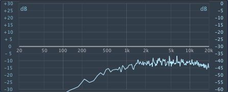
Makes a lot more sense  And now it puts out real white noise And now it puts out real white noise 
The schematic will follow as soon as I get hold of another problem:
I have a VCO in the circuit. But it bleeds into the noise. I sounds like there's a hipassed version of thenVCO output inside the noise. The sound is gone as soon as I disconnect the Pitch Pot from the VCO. Now I'm pretty stuck here.
Is there a way to stop the vco bleeding into the noise? I read something about decoupling and virtual ground on the web BUT I'm not quite sure how to get THAT into my circuit.
I have to say again that I'm new to all this... Could someone please point me into the right direction?
Thanks guys...
_________________
"I don't care much about music. What I like is sounds." |
|
|
Back to top
|
|
|
Rykhaard
Joined: Sep 02, 2007
Posts: 1290
Location: Canada
|
| Posted: Tue Apr 20, 2010 4:46 am Post subject:
|
|
|
| metal_head_82 wrote: |
I have a VCO in the circuit. But it bleeds into the noise. I sounds like there's a hipassed version of thenVCO output inside the noise. The sound is gone as soon as I disconnect the Pitch Pot from the VCO. Now I'm pretty stuck here.
Is there a way to stop the vco bleeding into the noise? I read something about decoupling and virtual ground on the web BUT I'm not quite sure how to get THAT into my circuit.
I have to say again that I'm new to all this... Could someone please point me into the right direction?
Thanks guys... |
A possible solution to the bleeding within the circuit, could possibly be due to each portion of the circuit wishing to have any available current for it's portion, immediately. With a few things happening at once, this could present an availability problem for the 'hydro company" where - they're no able to provide, that much current to everyone, at the same time; hence, the bleeding.
2 solutions for it would be:
- adding a 'buffer' capacitor so the entire circuit board itself, right where the power is coming in from the "hydro company" / battery / etc.
When there aren't too many components on the board, a capacitor between the values of 1 to 10uF would be fine. (And be sure to place the capacitor correctly, as to it's polarity:
For a +V buffer - the positive side of the capacitor to it and the other side of the cap. to Ground.
For a -V buffer - the negative side of the cap, to it and the other side of the cap. to Ground.
- Next, each chip should have a 'buffer' as well. Almost every time, a 0.1uF cap, as close to the power pin of the chip as possible, will be fine. Any cap really, from 0.01 to 0.1uF will be fine for this. (And yes - if it's a bipolar chip, a separate small cap., for each of that chip's power input pins.)
The bleeding problem I first knowing experienced in about 1991 / 1992, when I had my first LFO and Attack / Release enevelope generator, built, running and bleeding all over the place. A very good online electronics friend at that time, suggested adding a buffer cap to each of the circuit boards and at that time - away my bleeding problems went.
Keep up the good work! There're many helpful people here at EM. I've learned a heck of a lot more since I had first joined, the few years ago.
Welcome to electro-music!  |
|
|
Back to top
|
|
|
kkissinger

Joined: Mar 28, 2006
Posts: 1357
Location: Kansas City, Mo USA
Audio files: 42
|
| Posted: Tue Apr 20, 2010 8:25 am Post subject:
|
|
|
| metal_head_82 wrote: | | I have a VCO in the circuit. But it bleeds into the noise. I sounds like there's a hipassed version of then VCO output inside the noise. The sound is gone as soon as I disconnect the Pitch Pot from the VCO. |
Without viewing your schematic, I will presume that your pitch pot supplies a DC voltage to the VCO's input CV buss.
When you disconnect the pot, your are removing voltage from the buss that will change the frequency of your VCO. If the VCO's frequency becomes low it may still bleed to your noise circuit but will be inaudible.
I have read (though have never done it myself) that it may be advantageous to clip the base lead from the noise transistor at the transistor's case. Apparently, the base's lead can act as an antenna and pick up unwanted signals and impart them to the noise circuit.
Also, as already mentioned, you should include individual decoupling capacitors on your chips and across the circuit board.
_________________
-- Kevin
http://kevinkissinger.com |
|
|
Back to top
|
|
|
metal_head_82
Joined: Dec 27, 2009
Posts: 34
Location: Germany
Audio files: 2
|
| Posted: Wed Apr 21, 2010 2:05 am Post subject:
|
|
|
Thanks for the answers! 
But if I get the whole thing right I need a dual supply, right?
I'm currently using a 9V battery. Because I want this little thing for mobile use.
I will try to use a voltage divider and an OPamp to build a virtual ground. And then try buffering the ICs. If I'd do this now the ICs won't work.
So please tell me if I'm right with this... Dual supply + Buffering = Success???
Thanks
_________________
"I don't care much about music. What I like is sounds." |
|
|
Back to top
|
|
|
metal_head_82
Joined: Dec 27, 2009
Posts: 34
Location: Germany
Audio files: 2
|
| Posted: Wed Apr 21, 2010 3:47 am Post subject:
|
|
|
I made something up myself
I simply use an OPamp to buffer the supply voltage. I just use the remaining amp of the TL072 which amplifies the noise to feed the VCO.
Maybe it's not THAT ULTIMATE solution but at least it works - and until now without problems
Or do I have to be careful with such misuse of my OPamps???
What do you guys think about that?
_________________
"I don't care much about music. What I like is sounds." |
|
|
Back to top
|
|
|
|

 Forum index » DIY Hardware and Software » Developers' Corner