| Author |
Message |
Skrog Productions

Joined: Jan 07, 2009
Posts: 1220
Location: Scottish Borders
Audio files: 159
|
|
|
Back to top
|
|
 |
Skrog Productions
Joined: Jan 07, 2009
Posts: 1220
Location: Scottish Borders
Audio files: 159
|
|
|
Back to top
|
|
|
yusynth

Joined: Nov 24, 2005
Posts: 1314
Location: France
|
 Posted: Fri Jun 18, 2010 12:11 am Post subject: Posted: Fri Jun 18, 2010 12:11 am Post subject:
|
  |
|
Are you using scotchmark for your front panel ?
_________________
Yves |
|
|
Back to top
|
|
|
Skrog Productions
Joined: Jan 07, 2009
Posts: 1220
Location: Scottish Borders
Audio files: 159
|
| Posted: Fri Jun 18, 2010 5:27 am Post subject:
|
|
|
Hi Yves
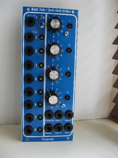
i get my panels done at my local sign makers workshop , lazer printed blue onto sticky back white vinyl , using soapy water to de-activate the adhesive till it lines up with the drill holes and left to dry , the bubbles are fast contracting , almost flat finish now its had a few days to stick.
going to de-bug the random gates , i think it may be the SCL4006 chip ,
Dave.. |
|
|
Back to top
|
|
|
yusynth
Joined: Nov 24, 2005
Posts: 1314
Location: France
|
| Posted: Fri Jun 18, 2010 7:14 am Post subject:
|
|
|
| Skrog Productions wrote: | Hi Yves
i get my panels done at my local sign makers workshop , lazer printed blue onto sticky back white vinyl , using soapy water to de-activate the adhesive till it lines up with the drill holes and left to dry , the bubbles are fast contracting , almost flat finish now its had a few days to stick.
going to de-bug the random gates , i think it may be the SCL4006 chip ,
Dave.. |
Thanks for the explainations.
Did you build the old or the lastest of the version of the RANDOM GATES?
_________________
Yves |
|
|
Back to top
|
|
|
Skrog Productions
Joined: Jan 07, 2009
Posts: 1220
Location: Scottish Borders
Audio files: 159
|
| Posted: Sat Jun 19, 2010 4:44 am Post subject:
|
|
|
Latest version , going to have another look today.
Dave. |
|
|
Back to top
|
|
|
Skrog Productions
Joined: Jan 07, 2009
Posts: 1220
Location: Scottish Borders
Audio files: 159
|
| Posted: Wed Jun 23, 2010 9:01 am Post subject:
|
|
|
hurrah !!! , working now , fault caused by a rubber chip from ebay , date marked 1984 made in Tiwan , got a couple of chips from Crickelwood date marked 1979 and it's working like a dream now .
Chuffed to bits 
Dave. |
|
|
Back to top
|
|
|
ricoloverde
Joined: Nov 09, 2009
Posts: 39
Location: berkeley
|
| Posted: Thu Feb 10, 2011 11:36 am Post subject:
|
|
|
Hi I cant get my Random Gates to work, Ive been over it a 100 times and cannot for the life me fig it out. My one concern is im using a HEF4006 when a cd4006 is required? think thats my issue?
EDIT: JUST SAW THAT THE HEF4006 IS A LISTED ALTERNATIVE. NOW IM REALLY STUMPED. |
|
|
Back to top
|
|
|
yusynth
Joined: Nov 24, 2005
Posts: 1314
Location: France
|
| Posted: Fri Feb 11, 2011 5:59 am Post subject:
|
|
|
| ricoloverde wrote: | Hi I cant get my Random Gates to work, Ive been over it a 100 times and cannot for the life me fig it out. My one concern is im using a HEF4006 when a cd4006 is required? think thats my issue?
EDIT: JUST SAW THAT THE HEF4006 IS A LISTED ALTERNATIVE. NOW IM REALLY STUMPED. |
Which PCB are you using ?
In the latest version of the PCB I added modifications in order to take care of the peculiarities of the HEF4006.
_________________
Yves |
|
|
Back to top
|
|
|
ricoloverde
Joined: Nov 09, 2009
Posts: 39
Location: berkeley
|
| Posted: Fri Feb 11, 2011 11:56 am Post subject:
|
|
|
im using the newest board from Bridechamber
edit: thanks Yves, somehow I missed that on your page for it. I swear Im slectively blind sometimes...will try that now. |
|
|
Back to top
|
|
|
ricoloverde
Joined: Nov 09, 2009
Posts: 39
Location: berkeley
|
| Posted: Fri Feb 11, 2011 12:06 pm Post subject:
|
|
|
| just to be sure, are those mods for the boards Bridechamber has? Im using one of those and the HEF4006 |
|
|
Back to top
|
|
|
yusynth
Joined: Nov 24, 2005
Posts: 1314
Location: France
|
| Posted: Fri Feb 11, 2011 12:12 pm Post subject:
|
|
|
Because I am no native English speaker I am not sure that my previous message was clear.
If you have the latest PCB from Bridechamber then it is perfectly suitable for use with the HEF4006. There is no modification to apply.
The mods shown at the bottom of the module's page only concern the very first version of the PCB that was never provided by Bridechamber.
Can you describe what is not working with your module ?
_________________
Yves |
|
|
Back to top
|
|
|
ricoloverde
Joined: Nov 09, 2009
Posts: 39
Location: berkeley
|
| Posted: Fri Feb 11, 2011 4:42 pm Post subject:
|
|
|
Hi Yves, thanks for the help. So far it wont really do anything. No life at all really. Im powering it off a synth.com power supply. I can see im getting power to each ic
I am getting 15v on pin 14 of the 4006, 15v on pin 16 for the 4051. Also on the 4051 i get 0v on C, 15v on B, and 0v on A
Ive gone thru every component, checked for shorts, and swapped out the ics for new ones |
|
|
Back to top
|
|
|
yusynth
Joined: Nov 24, 2005
Posts: 1314
Location: France
|
| Posted: Sat Feb 12, 2011 2:34 am Post subject:
|
|
|
Are you clocking it ? Have you plugged a LFO for example in the clock input ?
_________________
Yves |
|
|
Back to top
|
|
|
ricoloverde
Joined: Nov 09, 2009
Posts: 39
Location: berkeley
|
| Posted: Sat Feb 12, 2011 9:12 am Post subject:
|
|
|
| yes, i took those measurements while a gate out from a MFOS Sequencer was plug into it |
|
|
Back to top
|
|
|
ricoloverde
Joined: Nov 09, 2009
Posts: 39
Location: berkeley
|
| Posted: Sat Feb 12, 2011 12:28 pm Post subject:
|
|
|
Posted: Sat Feb 12, 2011 2:27 pm Post subject:
so i measured all the pins of the 4051 with a gate signal being fed in from a sequencer. gate switch set to legato. measuring from ground to each pin.
pins.
1 - 1.4
2 - 1
3 - 15
4 - 1.33
5 - 1.22
6 - 15
7 - 0
8 - 0
9 - 0
10 - 0
11 - 0
12 - 1.4
13 - 1.4
14 - 1.2
15 - 1.4
16 - 15 |
|
|
Back to top
|
|
|
yusynth
Joined: Nov 24, 2005
Posts: 1314
Location: France
|
| Posted: Sun Feb 13, 2011 12:41 pm Post subject:
|
|
|
Check with your voltmeter the voltage at pin 3 of the 4006 or pin 11 of the 4070 when clocking it at a 60BPM rate , you should measure 0V and 15V at a frequency of 1Hz , if not the problem is coming either from the 4070 or either from Q1,D1,R3,R4,R5. You can also check on the collector of Q1 (or pin 12 of the 4070).
_________________
Yves |
|
|
Back to top
|
|
|
ricoloverde
Joined: Nov 09, 2009
Posts: 39
Location: berkeley
|
| Posted: Mon Feb 14, 2011 1:38 pm Post subject:
|
|
|
will try that today. question for u about the resistor networks. i couldnt find any 9 pin (1 common + 8 legs) i have 10 pin (1 common + 9 legs) can I cut the last leg off as long as it isnt the common?
thanx Yves. |
|
|
Back to top
|
|
|
yusynth
Joined: Nov 24, 2005
Posts: 1314
Location: France
|
| Posted: Mon Feb 14, 2011 2:14 pm Post subject:
|
|
|
| ricoloverde wrote: | | i couldnt find any 9 pin (1 common + 8 legs) i have 10 pin (1 common + 9 legs) can I cut the last leg off as long as it isnt the common? |
Yes it is fine as long as you don't cut the common leg (it is marked by a dot)
_________________
Yves |
|
|
Back to top
|
|
|
|

 Forum index » DIY Hardware and Software » YuSynth