Joined: Nov 10, 2011 Posts: 878 Location: Lancashire, England
Audio files: 14
Posted: Fri Dec 23, 2011 4:18 pm Post subject:
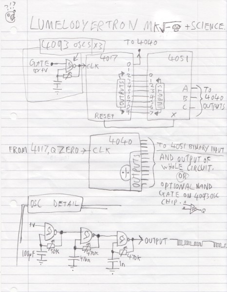
Lumelodyertron (based on a 4051 multiplexer) Subject description: current version: MK-4ish I think
I was talking about this in another thread. It's not entirely original but here it is, the Lumelodyertron. (see attachment for circuit diagram) The other designs I have seen for a similar circuit didn't use a VCO and didn't use a 4093 for the oscs.
You could have different 4093's gated by the 4051 instead of the voltage divider, the possibilities are great, I'll certainly be making modifications to this design.
The binary input oscillators are controlled by LDR's which change the tune depending on the light level. I used a bunch of random resistors in my divider so mine sounds a bit erratic, however I put them in order of size and ended up with a logarithmic voltage increase, like a hertz per volt keyboard of ye olde korgs.
I also considered driving the resistor chain with another LFO or some crazy waveform, however I ran out of gates on the 4093 chip, maybe next time I will use two for added madness
P.S. video to come soon.
melodyertron.png
Description:
MK1
Filesize:
10.97 KB
Viewed:
25531 Time(s)
Last edited by JingleJoe on Sat Jan 21, 2012 7:28 am; edited 3 times in total
Looks awesome! I'll be on the lookout for the video, and I'll try to breadboard it myself once the holiday madness dies down a bit. It looks really interesting!
Joined: Nov 10, 2011 Posts: 878 Location: Lancashire, England
Audio files: 14
Posted: Sat Dec 24, 2011 4:18 am Post subject:
This is about the first thing I did after I woke up, the sound isn't amazing I know but I was going for melody not madness I will add a madness control later but that'll mean about two more chips ... unless ... Hmm ... an OR gate could be the answer!
Yes, I think so!
[Caution, rambling ahead!]
My plan is to add a switch to the top of the resistor chain which allows the it to be fed with other waveforms, instead of the straight DC. The waveforms will be combined through an OR gate which solves some of the problems which would arise when using the charging waveform from the capacitors of an oscillator. I think the total resistance of the resistor chain and associated VCO is greater than 1Meg, so this should stop too much current being drawn from the caps, which would ruin thier oscillation. I could use that 7414 chip I have lying around too, mainly because I just want to get it used and rid of it, it's TTL and therefore difficult to make it work.
I like it! The most I've done with the 4051 is using it in the melody generator that I think slacker engineered. I've been intimidated by its datasheet so I haven't experimented with it at all, but this makes me want to...
Joined: Nov 10, 2011 Posts: 878 Location: Lancashire, England
Audio files: 14
Posted: Sun Dec 25, 2011 1:19 pm Post subject:
I could condense all the important bits of the datasheet for it into one paragraph:
three inputs (usually denoted A, B, C) use binary numbers to determine which of 8 other inputs/outputs is connected to the common connection (usually denoted "X") these can conduct either way, bi-directional, so they can be inputs or outputs or accept AC. Note that these connections have a small internal resistance of thier own which can vary depending on voltage/current etc.
I want to have a go with slacker's melody generator but I can't bloody well understand it but from what I read it should be able to do scales and things, dividing the input frequency by specific numbers, so instead of the divide by 2 4 8 etc we usually have with flip flops , it could divide by 3 or 5.... I think, someone tell me if I've got this right please
The melody generator works like this:
If you put a square wave into a 4017, it will divide by 10.
But when you connect output 5 to the reset, it will restart after 4,
and at the first output, you will have it divide by 4.
now, you use the 4051 to select which one of the outputs will connect to the reset.
so it will divide by the number made by inputs A, B and C.
Joined: Nov 10, 2011 Posts: 878 Location: Lancashire, England
Audio files: 14
Posted: Mon Dec 26, 2011 4:47 pm Post subject:
Oh I understand that, thats what it does ... but how? Whats acctually going on with that 4017 to make it divide by ten? I understand it's a counter, making each of the 10 outputs low in sequence when the clock signal progresses another cycle. But wouldn't that just be at the frequency of the clock? I don't understand how this would divide it by any number, surely the voltage from all the outputs combined would just be low constantly?
WAIT! I think I've got it, the output from the 4017 comes from it's own internal divider! which is can be cut short by it's own sequence ... great scott, my brain is working O_O I thought it was supposed to work worse after alcohol!? All this time I was lied to; Baileys is the key to all knowledge!
Joined: Nov 10, 2011 Posts: 878 Location: Lancashire, England
Audio files: 14
Posted: Mon Dec 26, 2011 5:28 pm Post subject:
Wait, forbget everything I said in the last message, the divide by 10 output ALLWAYS divides by 10 no matter when the chip is reset, I think I get it now though, please tell me if I get this right;
The 0 pin will give a pulse when the counter starts counting, the point at which it re-starts counting is determined by which output from the 4017 is connected to it's own reset. Subsequently, if pin 4 is connected to the reset, pin 0 will give a pulse every time the clock advances 4 cycles. So it's not real frequency division but rather "one pulse every so many steps" ... have I finally got it!?!?!?
Joined: Nov 10, 2011 Posts: 878 Location: Lancashire, England
Audio files: 14
Posted: Tue Dec 27, 2011 4:31 am Post subject:
Thankyou kabzoer thats bloody brilliant!
It seems hard to find a true divide-by-any-number circuit/IC, so I am currently inventing one ... by george I think I've got it!
One can simply add a flip flop to the 0 output to get true frequency divison! However, the added flip flop doubles the number the clock is divided by, so a divide by four becomes a divide by 8, 3 becomes 6, but how would one get divisions by the odd numbers then? ... oh acctually, I suppose it is still divides by the odd numbers but moved one octave down by the flip flop.
Joined: Nov 10, 2011 Posts: 878 Location: Lancashire, England
Audio files: 14
Posted: Thu Jan 05, 2012 11:22 am Post subject:
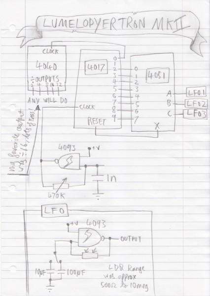
Here is a video of MK2 in action!
MK2 is still controled by light sensitive oscillators which provide the three binary inputs for the 4051, this version uses slacker's melody generator which is based on the 4017 and 4051, I added a few other chips (see above diagram). It divides the frequency of an initial oscillator by any number between 2 and 9, giving you the harmonic series of the frequency of the initial oscilator.
Short version: fun bleepy tunes! _________________ As a mad scientist I am ruled by the dictum of science: "I could be wrong about this but lets find out"
Joined: Nov 10, 2011 Posts: 878 Location: Lancashire, England
Audio files: 14
Posted: Thu Jan 05, 2012 3:45 pm Post subject:
slacker wrote:
Sounds great
Vindication from the creator! Thankyou, I couldn't have done it without you. Folks, a round of applause for the man himself; slacker! *clap clap clap* Thankyou for making this awesome circuit for me to play with, I have some great plans for it _________________ As a mad scientist I am ruled by the dictum of science: "I could be wrong about this but lets find out"
It sounds cool Jingle Joe! I dig the oscilloscope. I've gotta get one some time. Also, yeah Slacker, the melody generator has a permanent place on my lunetta board! (and in my heart)
It seems hard to find a true divide-by-any-number circuit/IC, so I am currently inventing one ... by george I think I've got it!
One can simply add a flip flop to the 0 output to get true frequency divison! However, the added flip flop doubles the number the clock is divided by, so a divide by four becomes a divide by 8, 3 becomes 6, but how would one get divisions by the odd numbers then? ... oh acctually, I suppose it is still divides by the odd numbers but moved one octave down by the flip flop.
Thankyou electro-music.com, for giving me this place to contemplate and formulate my ideas.
P.S. can anyone recomend a good 4000 series flip flop?
Hey Joe,
Nice sounds from the MKII.
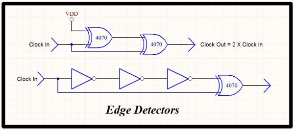
You can make a true divide by N by adding an edge detector to the circuit you have, it will give you a pulse out on all clock edges.
A 4013 D flip-flop is probably the easiest to use for the output but a 4027 JK will work too.
There is a divide by N chip, the 4018, but you don't really gain anything by using it as you need to add a mux and some gates to get the functionality you have with the 4017 and 4051 combo.
Edge_Detectors.JPG
Description:
Simple edge detectors.
Filesize:
62.18 KB
Viewed:
270 Time(s)
This image has been reduced to fit the page. Click on it to enlarge.
Joined: Nov 10, 2011 Posts: 878 Location: Lancashire, England
Audio files: 14
Posted: Sat Jan 07, 2012 12:13 pm Post subject:
They're rather good but I believe they just give a short pulse on each edge, correct? Nevertheless, very useful and I just got some XOR gates _________________ As a mad scientist I am ruled by the dictum of science: "I could be wrong about this but lets find out"
Yes, the edge detectors put out short pulses, but you insert it between the 4093 oscillator and the 4017 where the duty cycle doesn't matter and you can achieve true divide by N. It's a handy circuit when you need a 50% duty cycle output from a divide by N where N is an odd number.
Joined: Nov 10, 2011 Posts: 878 Location: Lancashire, England
Audio files: 14
Posted: Sun Jan 08, 2012 6:37 am Post subject:
AH, I see how it works now, thankyou! Very handy indeed, I'll add that to MK3 _________________ As a mad scientist I am ruled by the dictum of science: "I could be wrong about this but lets find out"
Joined: Nov 10, 2011 Posts: 878 Location: Lancashire, England
Audio files: 14
Posted: Fri Jan 13, 2012 4:54 pm Post subject:
Tried that 4070 XOR pulse generator circuit today, didn't work ... at first.
I summised that it uses the propagation delay to make the output pulse, but the delay must have been too short, to remedy this I put in a low pass filter to add a little phase shift which gave me an output pulse. However... when used to drive the 4017 it gave a wildly changing clock speed! The frequencies were all over the place! It was pretty much totally random- good for making some sort of random sequence generator, not good for accurate frequency division. _________________ As a mad scientist I am ruled by the dictum of science: "I could be wrong about this but lets find out"
Joined: Nov 10, 2011 Posts: 878 Location: Lancashire, England
Audio files: 14
Posted: Sun Jan 15, 2012 11:59 am Post subject:
Lumelodyertron of the space future!
I have recoreded a very long video of the Lumelodyertron MK Sqaure root of negative mushroom plus science. Yes it's that surreal and crazy. It's still uploading now so I will post it later but for now, here are the schematics.
I can't believe I got so much from just a few chips! I barely have any external components either, seriously just three capacitors and three resistors for the oscillators This slacker melody generator is brilliant, some would say ... magical!
Lumelodyertron_MK-Mushroom_schematics.jpg
Description:
It makes mario sounds :D And to clarify; osc is short for OSCillator
Filesize:
387.62 KB
Viewed:
308 Time(s)
This image has been reduced to fit the page. Click on it to enlarge.
_________________ As a mad scientist I am ruled by the dictum of science: "I could be wrong about this but lets find out"
Joined: Nov 10, 2011 Posts: 878 Location: Lancashire, England
Audio files: 14
Posted: Mon Jan 16, 2012 10:29 am Post subject:
Spacebones wrote:
Looking cool man. I wanna see the vid!
Thankyou, I tried to upload it to youtube but they deleted it because it was too long took bloody hours to upload, just to be told it's too long!
I'll chop it up and just post the start, it will still give everyone an idea of the kind of sounds it can make. _________________ As a mad scientist I am ruled by the dictum of science: "I could be wrong about this but lets find out"
Joined: Nov 10, 2011 Posts: 878 Location: Lancashire, England
Audio files: 14
Posted: Mon Jan 16, 2012 3:09 pm Post subject:
Finally! The video is chopped up and uploaded
This is a tangent really, I'll get back to my less crazy but still cool original plan soon ...
_________________ As a mad scientist I am ruled by the dictum of science: "I could be wrong about this but lets find out"
You cannot post new topics in this forum You cannot reply to topics in this forum You cannot edit your posts in this forum You cannot delete your posts in this forum You cannot vote in polls in this forum You cannot attach files in this forum You can download files in this forum

 Forum index » DIY Hardware and Software » Lunettas - circuits inspired by Stanley Lunetta


 It's still uploading now so I will post it later but for now, here are the schematics.