| Author |
Message |
Thomas_Henry
Joined: Jul 24, 2009
Posts: 170
Location: N. Mankato, MN
Audio files: 3
|
 Posted: Mon Aug 06, 2012 7:57 pm Post subject:
Voltage Controlled Crossfader/VCA Posted: Mon Aug 06, 2012 7:57 pm Post subject:
Voltage Controlled Crossfader/VCA
Subject description: Another circuit for your consideration |
  |
|
Hi Gang,
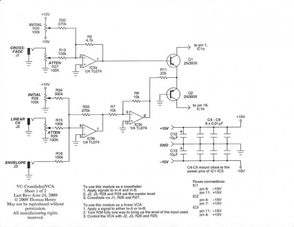
As promised, here is another circuit for you to play with. It can be used either as a voltage controlled crossfader or as an ordinary VCA. I hit upon this when finally realizing something that was in front of me all the time---the control currents though the voltage-to-current converter are symmetric yet opposite. It's an obvious idea once you see it and has probably been used before. But I was glad to stumble upon it.
Null out the DC thumps in the usual way. (Turn the audio inputs down, then apply a 0 to +5V square wave to the CV input.)
The usual legalese applies. Feel free to use this for personal applications but don't copy, or produce commercially. Anyone wanting to do a non-commercial PCB for EM users please contact me first.
Have fun!
Thomas Henry
| Description: |
|
| Filesize: |
53.57 KB |
| Viewed: |
3292 Time(s) |
| This image has been reduced to fit the page. Click on it to enlarge. |
|
| Description: |
|
| Filesize: |
77.2 KB |
| Viewed: |
3314 Time(s) |
| This image has been reduced to fit the page. Click on it to enlarge. |
|
| Description: |
|
| Filesize: |
51.65 KB |
| Viewed: |
1592 Time(s) |
| This image has been reduced to fit the page. Click on it to enlarge. |
|
|
|
|
Back to top
|
|
 |
v-un-v
Janitor


Joined: May 16, 2005
Posts: 8933
Location: Birmingham, England, UK
Audio files: 11
G2 patch files: 1
|
| Posted: Tue Aug 07, 2012 3:14 am Post subject:
|
|
|
Looks fun Mr Henry! Cheers! 
_________________
ACHTUNG!
ALLES TURISTEN UND NONTEKNISCHEN LOOKENPEEPERS!
DAS KOMPUTERMASCHINE IST NICHT FÜR DER GEFINGERPOKEN UND MITTENGRABEN! ODERWISE IST EASY TO SCHNAPPEN DER SPRINGENWERK, BLOWENFUSEN UND POPPENCORKEN MIT SPITZENSPARKSEN.
IST NICHT FÜR GEWERKEN BEI DUMMKOPFEN. DER RUBBERNECKEN SIGHTSEEREN KEEPEN DAS COTTONPICKEN HÄNDER IN DAS POCKETS MUSS.
ZO RELAXEN UND WATSCHEN DER BLINKENLICHTEN. |
|
|
Back to top
|
|
|
inlifeindeath

Joined: Apr 02, 2010
Posts: 316
Location: Albuquerque, NM
|
|
|
Back to top
|
|
|
widdly
Joined: Jun 25, 2007
Posts: 268
Location: singapore
G2 patch files: 2
|
Posted: Wed Nov 07, 2012 8:39 am Post subject:
 |
|
|
Thanks for another great design Thomas.
I built it this afternoon on perf board and it works very nicely. Like the other TH designs I've built, the input ranges on all the controls are tuned perfectly.
|
|
|
Back to top
|
|
|
fonik

Joined: Jun 07, 2006
Posts: 3950
Location: Germany
Audio files: 23
|
Posted: Tue Sep 22, 2015 5:17 am Post subject:
Re: Voltage Controlled Crossfader/VCA
Subject description: Another circuit for your consideration |
|
|
while looking around for a simple crossfader CV circuitry i found a very similiar on an old tom gamble EFM dual VCA, however, your solution is much more elegant and adds a nice touch with the overall volume control using the emitters!
thank you!
_________________

cheers,
matthias
____________
Big Boss at fonitronik
Tech Buddy at Random*Source |
|
|
Back to top
|
|
|
elmegil

Joined: Mar 20, 2012
Posts: 2179
Location: Chicago
Audio files: 16
|
| Posted: Tue Sep 22, 2015 7:07 am Post subject:
|
|
|
Excellent, thanks Thomas!
(Previous post deleted; still need the reminder not to post before finishing my tea) |
|
|
Back to top
|
|
|
Sethkaine
Joined: Sep 26, 2015
Posts: 16
Location: Suisse
|
| Posted: Mon Sep 28, 2015 2:48 am Post subject:
expo converter |
|
|
Hello Thomas,
I'm trying myself to your OTA designs : learning, breadboarding, etching, soldering, testing, listening. I love your designs from birthofsynth by the way. 
Sounds great to discover "new to my knowledge" designs in this forum. I'll going to try it out.
continue the good job and a big thank you for your schematics you're pleasing my ears.
_________________
my youtube channel - https://www.youtube.com/user/SethKaine/videos
my paper mix - https://paper.fiftythree.com/1865071 |
|
|
Back to top
|
|
|
wackelpeter
Joined: May 05, 2013
Posts: 461
Location: germany
Audio files: 10
|
| Posted: Tue Feb 02, 2016 12:20 pm Post subject:
|
|
|
Nice design Thomas, many thanks for that very cool circuit.
It's not only a Crossfader or VCA also some kind of manual or voltage controlled wavefolder/mangler when you feed two waveforms from one VCO into it.
Like it 
Makes me feel i need a second one... 
_________________
https://soundcloud.com/bastian-j |
|
|
Back to top
|
|
|
richardc64

Joined: Jun 01, 2006
Posts: 679
Location: NYC
Audio files: 26
|
|
|
Back to top
|
|
|
LFLab
Joined: Dec 17, 2009
Posts: 497
Location: Rosmalen, Netherlands
|
| Posted: Wed Feb 03, 2016 3:58 am Post subject:
|
|
|
| Which IS very interesting! Have you tried this with the LM13700 schematic already, Richard? |
|
|
Back to top
|
|
|
roglok

Joined: Aug 28, 2010
Posts: 202
Location: uptown
|
| Posted: Wed Feb 03, 2016 8:22 am Post subject:
|
|
|
thanks for the reminder, richard. i've meant to prototype your circuit but totally forgot about it... |
|
|
Back to top
|
|
|
richardc64
Joined: Jun 01, 2006
Posts: 679
Location: NYC
Audio files: 26
|
| Posted: Fri Feb 05, 2016 8:13 am Post subject:
|
|
|
| LFLab wrote: | | Which IS very interesting! Have you tried this with the LM13700 schematic already, Richard? |
Negative, LF. I have other priorities. But anyone is welcome come to experiment with the idea: Capacitor couple the audio inputs, give it a better current source, perhaps with Lin-Log response.
Etc.
_________________
Revenge is a dish best served with a fork... to the eye |
|
|
Back to top
|
|
|
wackelpeter
Joined: May 05, 2013
Posts: 461
Location: germany
Audio files: 10
|
| Posted: Fri Feb 05, 2016 11:35 am Post subject:
|
|
|
| richardc64 wrote: | | LFLab wrote: | | Which IS very interesting! Have you tried this with the LM13700 schematic already, Richard? |
Negative, LF. I have other priorities. But anyone is welcome come to experiment with the idea: Capacitor couple the audio inputs, give it a better current source, perhaps with Lin-Log response.
Etc. |
Damn... that's what i forgot on my TH X-Fader because i couldn't wait to test it.... didn't recognized the two blank holes on my frontpanel...
_________________
https://soundcloud.com/bastian-j |
|
|
Back to top
|
|
|
sompost
Joined: Aug 17, 2010
Posts: 58
Location: Switzerland
|
| Posted: Sat Feb 27, 2016 2:58 am Post subject:
Crossfader-only |
|
|
Hi all,
I would like to use this great circuit as a voltage controlled mixer (crossfader option on sheet 1 above). Because the master level would always be set to maximum level, and envelope control would not be needed, the whole branch to the left of R11 (between Q1 and Q2) seems unnecessary for a crossfader-only use. Am I right?
What would I have to replace that branch with? Do I need the buffer (IC3c) or can I just supply +15V via some resistance to the point between Q1 and Q2? What would that resistance be?
Thanks!
_________________
Built: MFOS SLMS plus, SL Ultimate & Expander, 10 step seq; SLMS MkII; PAiA FatMan, Mutable-Instruments Shruthi-1; Jasper Wasp Clone
Building: Maddox MonoWave; Auduino; ASM-2; Minimoog Clone
Backlogging: MFOS 16 step seq; TH SN Voice; Takeda One Board Farm; Okita Vocoder; Page TR-9090; TH GM Voice, AY Voice |
|
|
Back to top
|
|
|
4b11b4
Joined: Sep 17, 2016
Posts: 1
Location: Oregon
|
| Posted: Sat Sep 17, 2016 12:47 pm Post subject:
Re: Crossfader-only |
|
|
| sompost wrote: | Hi all,
I would like to use this great circuit as a voltage controlled mixer (crossfader option on sheet 1 above). Because the master level would always be set to maximum level, and envelope control would not be needed, the whole branch to the left of R11 (between Q1 and Q2) seems unnecessary for a crossfader-only use. Am I right?
What would I have to replace that branch with? Do I need the buffer (IC3c) or can I just supply +15V via some resistance to the point between Q1 and Q2? What would that resistance be?
Thanks! |
Did you ever build this? |
|
|
Back to top
|
|
|
LFLab
Joined: Dec 17, 2009
Posts: 497
Location: Rosmalen, Netherlands
|
| Posted: Sun Sep 18, 2016 1:01 am Post subject:
|
|
|
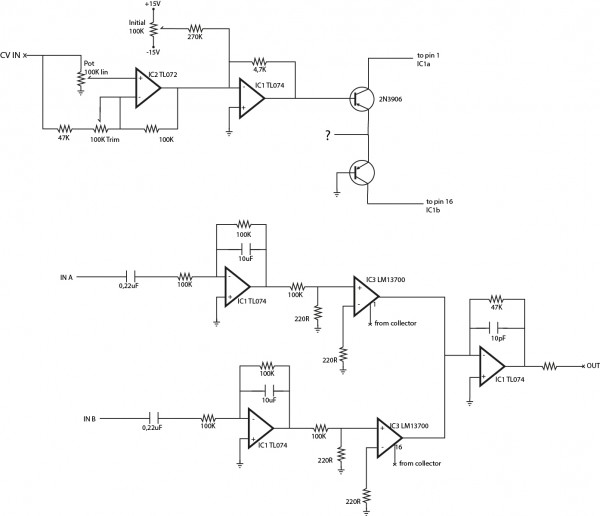
By the way, I have built RichardC64's version with LM13700, and it works fine.
Forgot to add capacitors to the audio inputs though, and I haven't calibrated it yet, but it does work. (let me know if you'd like a few boards Richard). |
|
|
Back to top
|
|
|
sompost
Joined: Aug 17, 2010
Posts: 58
Location: Switzerland
|
| Posted: Sun Sep 18, 2016 6:39 am Post subject:
Re: Crossfader-only |
|
|
| 4b11b4 wrote: | | Did you ever build this? |
No, I didn't. First, I've got plenty of other unfinished business to do, and second I dropped the voltage controlled mixer from the design.
Ralph
_________________
Built: MFOS SLMS plus, SL Ultimate & Expander, 10 step seq; SLMS MkII; PAiA FatMan, Mutable-Instruments Shruthi-1; Jasper Wasp Clone
Building: Maddox MonoWave; Auduino; ASM-2; Minimoog Clone
Backlogging: MFOS 16 step seq; TH SN Voice; Takeda One Board Farm; Okita Vocoder; Page TR-9090; TH GM Voice, AY Voice |
|
|
Back to top
|
|
|
richardc64
Joined: Jun 01, 2006
Posts: 679
Location: NYC
Audio files: 26
|
| Posted: Mon Sep 19, 2016 8:45 am Post subject:
|
|
|
| LFLab wrote: | By the way, I have built RichardC64's version with LM13700, and it works fine.
Forgot to add capacitors to the audio inputs though, and I haven't calibrated it yet, but it does work. (let me know if you'd like a few boards Richard). |
That's great, LFLab. It's good to know that that past success wasn't a fluke. What values did you use for the Initial CV pot and the mystery resistor?
As for boards... Thanks for the offer, but I dunno. My prototype is still collecting dust, here. I'll let you know.
_________________
Revenge is a dish best served with a fork... to the eye |
|
|
Back to top
|
|
|
LFLab
Joined: Dec 17, 2009
Posts: 497
Location: Rosmalen, Netherlands
|
| Posted: Tue Sep 20, 2016 3:21 am Post subject:
|
|
|
Not sure what the mystery resistor is (maybe I should read everything before plonking something in Eagle ), but this is what I have now, no wiring needed.

The lower section is one of Ray's (MFOS) VCA's.
(sorry for the OT discussion) |
|
|
Back to top
|
|
|
richardc64
Joined: Jun 01, 2006
Posts: 679
Location: NYC
Audio files: 26
|
| Posted: Tue Sep 20, 2016 6:21 pm Post subject:
|
|
|
| LFLab wrote: | | Not sure what the mystery resistor is... |
Oops. I neglected to include it in the 13700 schema. In the 3080 version it's at the -v end of the Initial CV pot. It's supposed to offset the range of that pot so that with no CV, when the pot is in the centered position a signal on Xin or Yin is at equal levels on both outputs.
I like that you included a normal VCA on your board. I may want one after all
_________________
Revenge is a dish best served with a fork... to the eye |
|
|
Back to top
|
|
|
Cfish

Joined: Feb 24, 2016
Posts: 477
Location: Indiana
|
| Posted: Wed Sep 21, 2016 6:22 pm Post subject:
|
|
|
Thank you Thomas.
so much of my modular is built from your schematics. I know I can perfboard them up and count on them to work.
That always means a lot to me. Will give this one a try. |
|
|
Back to top
|
|
|
VinL
Joined: Jan 24, 2017
Posts: 1
Location: Québec
|
| Posted: Tue Jan 24, 2017 12:06 pm Post subject:
|
|
|
First post!
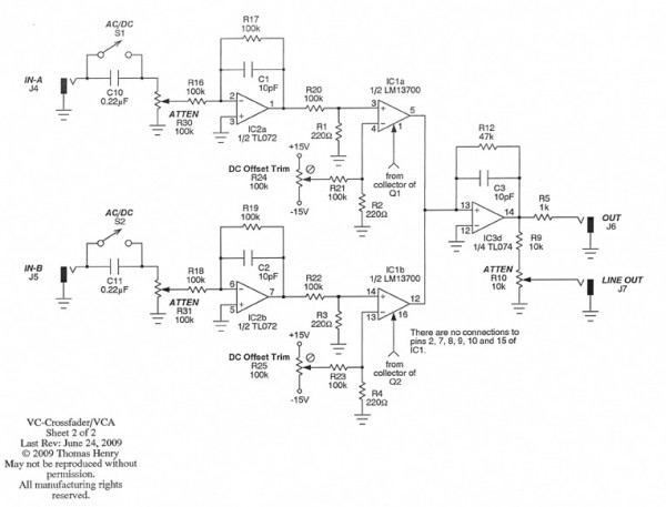
I've found a minor mistake in the crossfader/vca schematic. On the schematic pin 13 of the TL074 is labelled as the non-inverting input and pin 12 as the inverting input whereas it should be the opposite. I was actually building a dual version of vca-1, wich is very similar, with lm13700 and using both schematics got me stumbling on this anomaly.
BTW I love Thomas Henry designs!!! My favorites since I got into synth DIY about a year ago. |
|
|
Back to top
|
|
|
Thomas_Henry
Joined: Jul 24, 2009
Posts: 170
Location: N. Mankato, MN
Audio files: 3
|
| Posted: Tue Jan 24, 2017 8:54 pm Post subject:
|
|
|
Thanks for pointing that out.
To be clear, everyone, the pinout in the schem is correct, so build away! Only the plus and minus signs in the op-amp representation of IC3d are reversed.
Thomas Henry |
|
|
Back to top
|
|
|
ReToxx
Joined: Dec 06, 2016
Posts: 8
Location: Germany
|
| Posted: Tue Feb 14, 2017 3:18 pm Post subject:
|
|
|
Hello everybody,
I want to build a small circuit wich allows me to feed back the normal output and the inverted one of a filter back to its input by a voltage controlled crossfader. So i want to have a knob which has no output in its middle position,
full ccw would be the inverted only (which also means no output at the output;-) ), full cw would be the normal output. And I also want cv control over the crossfading, where the knob acts as a starting point for the cv...
I want to leave as much as possible, but I don't know how to deal with that amp stuff thats going to in between the two transistors...
I already left the ac/dc switch, and the attenuators at the inputs, as well as the dc offset trimmers, as i will use it only for audio. And i added an attenuverter at the cv in...
don't know if that all makes sense and what to do with the input at the transistor, maybe i could only leave the initial gain pot as a trimmer, but to what value do i have to trimm that? or can i somehow set a voltage right at the transistors and get rid of the opamps there...
thanks so much for any advice
| Description: |
|
| Filesize: |
160.44 KB |
| Viewed: |
823 Time(s) |
| This image has been reduced to fit the page. Click on it to enlarge. |
|
|
|
|
Back to top
|
|
|
fonik
Joined: Jun 07, 2006
Posts: 3950
Location: Germany
Audio files: 23
|
| Posted: Tue Feb 14, 2017 10:55 pm Post subject:
|
|
|
| ReToxx wrote: | | I want to leave as much as possible, but I don't know how to deal with that amp stuff thats going to in between the two transistors... |
i used 20k there (from +12V).
_________________
cheers,
matthias
____________
Big Boss at fonitronik
Tech Buddy at Random*Source |
|
|
Back to top
|
|
|
|

 Forum index » DIY Hardware and Software » Thomas Henry designs
