| Author |
Message |
PHOBoS

Joined: Jan 14, 2010
Posts: 5947
Location: Moon Base
Audio files: 709
|
 Posted: Tue Dec 24, 2013 7:43 pm Post subject: Posted: Tue Dec 24, 2013 7:43 pm Post subject:
|
  |
|
yesterday I wired up the patchmatrix, which actually went quicker then I expected, and mounting the PCB turned out too be pretty easy too 
I only had time for a short test, and allthough it seemed to be working (without any smoke) I noticed 3 problems.
The first problem was that AD/AR generator 1 sometimes doesn't work. I had noticed this before I installed the patchmatrix and tested all the
modules. But I thought I solved it after removing a bit of solder, so I guess that wasn't it. The fact that it's an intermittent problem makes
it hard to find, but maybe it's just a bad chip (it worked before though). So I'll try replacing it and see if that helps.
The second problem was that I got some weird behaviour from the patchmatrix. For instance when I patched the PWLFO to OSC I, not only did OSC
get triggered but AD/AR 1, AD/AR 2 and the random generator aswell. And this happened with several combination but not in a way that some things
could be shorted, And everything seems to be wired up in the correct order.
The third problem was that it produces absolutly no sound,. no buzzing either so that's a plus. But the fact that it's silent makes me think
it might be something very simple like a connection on the PCB I forgot, or maybe just a bad cable going to the output jack. I did try
listening to all the outputs using the patchmatrix, and that works as expected.
I just had some time to do more testing to see if I could figure out what's wrong with the patchmatrix. Since the inputs of all the
modules are directly connected to the outputs of CMOS gates then whatever is causing it is having an effect on those gates, either on the
inputs or through the power (or internal). When the inputs aren't patched up they should get pulled to a low state, which is why a used a 47K
pulldown and 100K pullup resistor. So I decided to do some measurements:
On the inputs that are directly connected to the 47K pulldown resistor I measured 3.58V and on the other inputs, connected to the 100K
pullup and through the diodes to the 47K pulldown resistor, I measured 4.38V.
So I had a look at the datasheet and for the chip I used (ST Microelectronics HCF4081) it states that the maximum low level voltage is
3V @ 10V Vdd and 4V @ 15V Vdd, so with a voltage of 12V it should be somewhere in between. The 3.58V might just do but the 4.38 is too high and
could cause problems. So I made some new calculations setting the max voltage at 3V and for that I had to replace the 100K pullup resistors with
200K ones. I just did another test, and now the patchmatrix works perfect  no more false triggering and the AND function when patching more no more false triggering and the AND function when patching more
outputs to one input works too. Also the connectors might not be so bad afterall, as I mentioned they don't really fit, but do just make contact
when just slightly pushed on, which also makes them easy to remove.
I'm going to try another chip in the ADAR generator now to see if that helps, and I hope to solve the audio problem in the next 2 days, or else in
the weekend. (I want to have it fully working before the end of the year  ) )
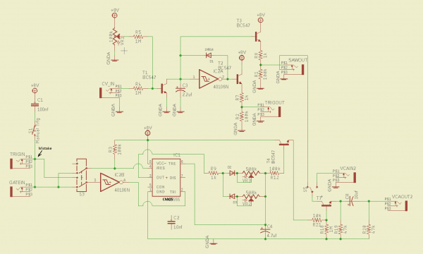
| Description: |
| the Moon Base Xplorer: updated patchmatrix schematic |
|
| Filesize: |
140.45 KB |
| Viewed: |
936 Time(s) |
| This image has been reduced to fit the page. Click on it to enlarge. |
|
_________________
"My perf, it's full of holes!"
http://phobos.000space.com/
SoundCloud BandCamp MixCloud Stickney Synthyards Captain Collider Twitch YouTube |
|
|
Back to top
|
|
 |
PHOBoS
Joined: Jan 14, 2010
Posts: 5947
Location: Moon Base
Audio files: 709
|
| Posted: Wed Dec 25, 2013 7:10 am Post subject:
|
|
|
After a bit more cleaning with a small screwdriver and a brush ADAR 1 seems to be working now, but I thought that the last time,. so I'll see what
happens after some more testing. I also got sound now, allthough I didn't get any magic smoke I did feel some heat coming from the VC mixer /delay
PCB  . Turned out I had inserted the quad opamp the wrong way, ahum,. and for some reason this fried the delay chip which got prettty warm. . Turned out I had inserted the quad opamp the wrong way, ahum,. and for some reason this fried the delay chip which got prettty warm. 
Luckely I do have another one of those chips but before I'm going to test that there is something else which isn't right; the output from the VCO SUB
channel is much softer then the other channels (VC mixer seems to work fine btw). It's correct up to the buffer opamp (voltage follower) but there's not
much coming out of it. It could be that the input voltage is just too high, so I am going to try adding a voltage divider (I can always amplify it more in the
mixer section if needed).
edit: replacing the opamp fixed it, and with a new chip the delay works too

_________________
"My perf, it's full of holes!"
http://phobos.000space.com/
SoundCloud BandCamp MixCloud Stickney Synthyards Captain Collider Twitch YouTube |
|
|
Back to top
|
|
|
PHOBoS
Joined: Jan 14, 2010
Posts: 5947
Location: Moon Base
Audio files: 709
|
| Posted: Wed Dec 25, 2013 3:35 pm Post subject:
|
|
|
So far everything seems to be working now.
But there are 2 things I might change, first of all the random/noise generator has an on/off switch that disconnects the CLK input. For the analog output
this is very usefull because I can put it on hold at a certain CV output, however the digital output can be high or low. So I'm thinking about installing a double
pole switch that turns off the digital output aswell. The other thing is the gate input on the VCO, right now I always have to patch up something to turn it
on and the only thing I can use that doesn't oscillate is the PWLFO at a 100/0 pulsewidth. but then I can't use it for anything else. Installing a switch is not
really an option, I mean it's possible but has a high risk of damaging the front. But I might be able to change the patchmatrix to have a high output
for the VCO gate when nothing is plugged in.
I also have to short all the connectors for the patchmatrix, else they won't do anything of course. But just for fun I tested what happens when you do
it with an LED and with a bright low current one (like blue) they actually light up or blink no idea what happens when you use a bunch at
once and it might get a bit too confusing with so many LED's, but worth a try I think.
_________________
"My perf, it's full of holes!"
http://phobos.000space.com/
SoundCloud BandCamp MixCloud Stickney Synthyards Captain Collider Twitch YouTube |
|
|
Back to top
|
|
|
PHOBoS
Joined: Jan 14, 2010
Posts: 5947
Location: Moon Base
Audio files: 709
|
Posted: Wed Dec 25, 2013 6:03 pm Post subject:
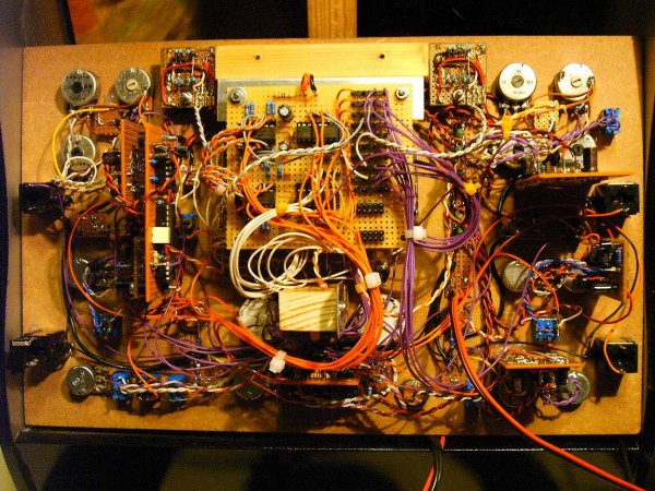
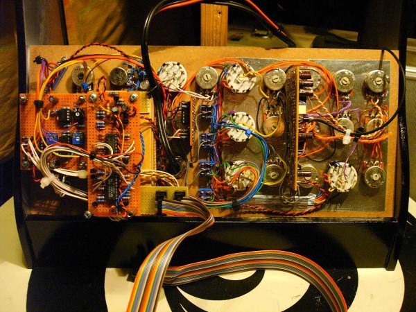
the Moon Base Xplorer
Subject description: wiring pics |
|
|
some photo's of the wiring on the backside of the panels. I'm out of small cable ties so the big panel is a bit of a mess,. allthough it will probably not
make a whole lot of a difference.
| Description: |
|
| Filesize: |
168.26 KB |
| Viewed: |
853 Time(s) |
| This image has been reduced to fit the page. Click on it to enlarge. |
|
| Description: |
|
| Filesize: |
157.9 KB |
| Viewed: |
855 Time(s) |
| This image has been reduced to fit the page. Click on it to enlarge. |
|
_________________
"My perf, it's full of holes!"
http://phobos.000space.com/
SoundCloud BandCamp MixCloud Stickney Synthyards Captain Collider Twitch YouTube |
|
|
Back to top
|
|
|
DUBmatze

Joined: Feb 18, 2013
Posts: 150
Location: south Germaica (schwabilon)
|
|
|
Back to top
|
|
|
PHOBoS
Joined: Jan 14, 2010
Posts: 5947
Location: Moon Base
Audio files: 709
|
| Posted: Thu Dec 26, 2013 8:54 am Post subject:
|
|
|
| PHOBoS wrote: | After a bit more cleaning with a small screwdriver and a brush ADAR 1 seems to be working now, but I thought that the last time,. so I'll see what
happens after some more testing. |
nope that wasn't it. So I just replaced the the transistor that's connected to the trigger input of the 555 and that seems to have solved it,. (I hope)
some extra about info about this transistor: when I was trying to find out why the ADAR wasn't working before I noticed that in AD mode the transistor is
always 'on', and therefor the trigger input of the 555 is low. I did some calculations and measurements and the voltage at the base is ±1V which
get's pulled down to .65 by the transistor. So apparently you can trigger a 555 by holding the trigger input at a low level and making the reset input
high. In AR mode the transistor switches as it should.
The patchconnectors with LED's are great ,. it actually makes it pretty easy to see which connector is doing what. And because they are diodes
the AND function doesn't work when using multiple connectors, instead it becomes an OR gate. So now I have even more options
I swapped the pullup/pulldown resistors in the patchmatrix for the VCO gate output (so it's on with nothing connected) and because of this the
LED's hardly light up when used there. But that's an extra bonus anyway.
oh and a flickering teacandle LED works too
| Description: |
|
| Filesize: |
408.6 KB |
| Viewed: |
555 Time(s) |
| This image has been reduced to fit the page. Click on it to enlarge. |

|
| Description: |
| Moon Base Xplorer sounds. |
|

Download (listen) |
| Filename: |
PHOBoS - Moon Base Xplorer - Moon Base Xplorations 00 (Dec 26, 2013).mp3 |
| Filesize: |
5.31 MB |
| Downloaded: |
1708 Time(s) |
| Description: |
| Moon Base Xplorer sounds. |
|
Download (listen) |
| Filename: |
PHOBoS - Moon Base Xplorer - Moon Base Xplorations 01 (Dec 26, 2013).mp3 |
| Filesize: |
11.32 MB |
| Downloaded: |
1724 Time(s) |
_________________
"My perf, it's full of holes!"
http://phobos.000space.com/
SoundCloud BandCamp MixCloud Stickney Synthyards Captain Collider Twitch YouTube
Last edited by PHOBoS on Sat Nov 17, 2018 6:24 pm; edited 1 time in total |
|
|
Back to top
|
|
|
richardc64

Joined: Jun 01, 2006
Posts: 679
Location: NYC
Audio files: 26
|
Posted: Thu Dec 26, 2013 9:33 am Post subject:
Re: the Moon Base Xplorer
Subject description: wiring pics |
|
|
Dude...is this some kind of d.i.y. marathon?
| PHOBoS wrote: | | I'm out of small cable ties so the big panel is a bit of a mess... |
I use insulated solid wire as twist-ties.
_________________
Revenge is a dish best served with a fork... to the eye |
|
|
Back to top
|
|
|
PHOBoS
Joined: Jan 14, 2010
Posts: 5947
Location: Moon Base
Audio files: 709
|
|
|
Back to top
|
|
|
PHOBoS
Joined: Jan 14, 2010
Posts: 5947
Location: Moon Base
Audio files: 709
|
|
|
Back to top
|
|
|
PHOBoS
Joined: Jan 14, 2010
Posts: 5947
Location: Moon Base
Audio files: 709
|
|
|
Back to top
|
|
|
PHOBoS
Joined: Jan 14, 2010
Posts: 5947
Location: Moon Base
Audio files: 709
|
|
|
Back to top
|
|
|
PHOBoS
Joined: Jan 14, 2010
Posts: 5947
Location: Moon Base
Audio files: 709
|
|
|
Back to top
|
|
|
Zodiak

Joined: May 20, 2007
Posts: 249
Location: Gillingham, Kent UK
|
| Posted: Thu Jan 02, 2014 7:10 am Post subject:
|
|
|
Thanks PHOBos, reading that has brought a huge smile to my face
_________________
Stephen
www.Rainsbury.Net |
|
|
Back to top
|
|
|
RingMad

Joined: Jan 15, 2011
Posts: 430
Location: Montreal, Canada
Audio files: 4
|
| Posted: Sun Jan 05, 2014 6:31 am Post subject:
|
|
|
Once again an amazing build, PHOBoS! I like your attention to detail. And thanks for posting the construction details... I'm sure some of those circuits will come in handy one day.
-- James. |
|
|
Back to top
|
|
|
PHOBoS
Joined: Jan 14, 2010
Posts: 5947
Location: Moon Base
Audio files: 709
|
|
|
Back to top
|
|
|
RF

Joined: Mar 23, 2007
Posts: 1502
Location: Northern Minnesota, USA
Audio files: 28
|
| Posted: Tue Jan 07, 2014 5:26 pm Post subject:
|
|
|
Really nice job and great sounds. Congrats!
_________________
www.sdiy.org/rfeng
"I want to make these sounds that go wooo-wooo-ah-woo-woo.”
(Herb Deutsch to Bob Moog ~1963) |
|
|
Back to top
|
|
|
PHOBoS
Joined: Jan 14, 2010
Posts: 5947
Location: Moon Base
Audio files: 709
|
|
|
Back to top
|
|
|
Ruebezahl

Joined: Mar 09, 2014
Posts: 112
Location: Taiwan
Audio files: 4
|
| Posted: Tue Sep 30, 2014 6:57 pm Post subject:
|
|
|
Just want to tell that i love this project. Its really inspiring!
_________________
https://soundcloud.com/ruebezahl |
|
|
Back to top
|
|
|
PHOBoS
Joined: Jan 14, 2010
Posts: 5947
Location: Moon Base
Audio files: 709
|
|
|
Back to top
|
|
|
isak

Joined: Dec 13, 2009
Posts: 847
Location: Israel
Audio files: 18
|
| Posted: Mon Oct 13, 2014 1:32 pm Post subject:
|
|
|
Hi PHOBoS this is amazing work
looks like Arcade synth 
Well done!
Cheers,
Isak.
_________________
http://www.myspace.com/mgmtrance |
|
|
Back to top
|
|
|
PHOBoS
Joined: Jan 14, 2010
Posts: 5947
Location: Moon Base
Audio files: 709
|
|
|
Back to top
|
|
|
beepetc.
Joined: Mar 07, 2018
Posts: 6
Location: Denmark
|
|
|
Back to top
|
|
|
PHOBoS
Joined: Jan 14, 2010
Posts: 5947
Location: Moon Base
Audio files: 709
|
| Posted: Sat Jul 21, 2018 11:36 am Post subject:
|
|
|
hi beepetc. 
It Looks like you made the AD/AR from the Lun-A-Key which is very similar.

Not drawn in this schematic is a capacitor connected to the trigger input because for that one I used a seperate circuit
to create a short pulse instead. so for reference here's the one from the Moon Base Xplorer which does have that capacitor.

The transistor and the resistors connected to it just act as an inverter so it works the same as using the 40106. However in
the Lun-A-Key the gate/trigger input is hardwired to the output of a 555, in your case you should add a resistor (~100K) to
Ground at the input of the inverter (pin3 of IC2B). This might solve the problems you are experiencing right now.
Also the manual trigger won't work they way you've drawn it, you won't need that capacitor so you can connect the switch directly
to the input, but you should add a diode in series with the gate/trigger input so it doesn't cause any problems if you use the maual
trigger with something else plugged in.
For testing to see if it works correct I would disconnect T4 and measure the voltage over C4, this way you can be certain
that it is not something else creating any problems.
and yes, this place is awesome
(it's perfectly fine to post here although a seperate thread might get a little bit more attention, but people in this lunetta section
usually seem to find every recent post)
_________________
"My perf, it's full of holes!"
http://phobos.000space.com/
SoundCloud BandCamp MixCloud Stickney Synthyards Captain Collider Twitch YouTube |
|
|
Back to top
|
|
|
beepetc.
Joined: Mar 07, 2018
Posts: 6
Location: Denmark
|
| Posted: Thu Jul 26, 2018 4:54 pm Post subject:
|
|
|
The gate/trig problem was a mistake, when we transferred the pencil-drawing to eagle. Thanks for pointing the OR combiner out, I don't know how I could miss it. <3 I guess I couldn't see the forest for the trees.
| Quote: | The transistor and the resistors connected to it just act as an inverter so it works the same as using the 40106. However in
the Lun-A-Key the gate/trigger input is hardwired to the output of a 555, in your case you should add a resistor (~100K) to
Ground at the input of the inverter (pin3 of IC2B). This might solve the problems you are experiencing right now. |
That worked! No more unstable looping envelope. Thank you!
The VCA is acting strange, so does the EG. It retriggers after release. But it does sends the voltage at the VCA out, sky high and doesn't let the sound from the oscillator out, until the release has come down. I'll fiddle around with the breadboard after the weekend, to see what happens if I change the resistor values connected to T4 and T7. I tried building another board, with had sound bleeding through T7 and no results with the AR, so I have to fool around with it a bit more.
Thanks for the fast and helpful response. c: |
|
|
Back to top
|
|
|
PHOBoS
Joined: Jan 14, 2010
Posts: 5947
Location: Moon Base
Audio files: 709
|
|
|
Back to top
|
|
|
|

 Forum index » DIY Hardware and Software


 . I've also done the lacing thing using stranded wire, it's a bit more work, but usually gives very nice results.