| Author |
Message |
SC

Joined: Apr 20, 2015
Posts: 10
Location: US
|
 Posted: Mon Apr 20, 2015 3:48 pm Post subject:
Re: ChipTune music box Posted: Mon Apr 20, 2015 3:48 pm Post subject:
Re: ChipTune music box
Subject description: simple chip tune generator |
  |
|
| synaesthesia wrote: | The CHIPTUNE circuit plays a small tune that repeats endlessly. The tune is surprisingly long and generates harmonic tones in interesting self-similar sequences. After a while you will start to follow the melody of the tune.
:::::
The generated melodies can be varied a bit by connecting Q1 to Q3 from the shift register to inputs A,B,C of U4 in different permutations.
Permutation Q3->A, Q2->B, Q1->C is used in the schematic. My favorite is Q2-A,Q3->B,Q1->C. I attached a recording for both tunes for your listening pleasure. |
Thank you very much for posting this circuit. Even though I am relatively new to electronics, I was able to put this circuit together in about an hour on a breadboard. It worked the first time time I plugged it in. Yay !!! It sounds great. (^_^) |
|
|
Back to top
|
|
 |
SC
Joined: Apr 20, 2015
Posts: 10
Location: US
|
Posted: Mon Apr 27, 2015 8:10 am Post subject:
Re: Super ChipTune
Subject description: A Thank-you note. |
|
|
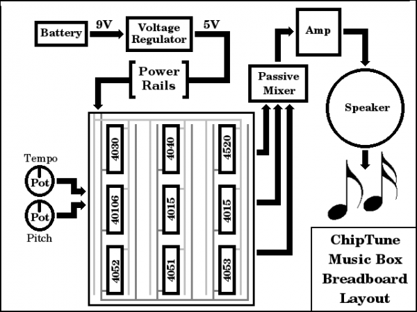
I have completed both Super ChipTune (with the 4053) and Super ChipTune 2 (with the 4052) on the breadboard. Both of them are really nice. There are a couple of places where Super ChipTune seems to hang a little, but I guess that is a part of the pattern. The Super ChipTune 2 circuit plays all the way through without 'hanging' at any one place. Very nice.
Both of these circuits have very nice schematics, which were very easy for me to breadboard. I have had so much fun building ChipTune, and both of the Super ChipTune circuits. I am looking forward to trying more of these Chip Tune Music Box circuits. These circuits are a wonderful introduction to Lunetta. Thanks !!!
(^_^) |
|
|
Back to top
|
|
|
synaesthesia

Joined: May 27, 2014
Posts: 291
Location: Germany
Audio files: 85
|
| Posted: Mon Apr 27, 2015 9:33 am Post subject:
|
|
|
Thanks for your nice feedback, SC! This is great motivation for me to continue sharing my circuits. I have no immediate explanation for the hangs you observed. I guess these are simply part of the melody that is generated by stepping through the divisions determined by the selected feedback term.
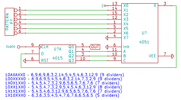
Just realized that I never posted the table of possible dividers that you can get with the core circuit with a 4051 and half of a 4015. Read the inputs X1 to X6 as a binary number, with X6 being the least significant bit. Look for that number in the fields with grey background and find the divider to the right of it. X0 must always be high and X7 must always be low to avoid any hangs. Any three out of the four outputs of the 4015 may be used, the results will only differ in the phase of the wave form. In the schematic there is also a list of simple input terms that use only four of the six possible inputs.
| Description: |
|
| Filesize: |
13.26 KB |
| Viewed: |
613 Time(s) |
| This image has been reduced to fit the page. Click on it to enlarge. |

|
| Description: |
|
| Filesize: |
27.79 KB |
| Viewed: |
620 Time(s) |
| This image has been reduced to fit the page. Click on it to enlarge. |
|
|
|
|
Back to top
|
|
|
SC
Joined: Apr 20, 2015
Posts: 10
Location: US
|
| Posted: Tue Apr 28, 2015 10:53 am Post subject:
|
|
|
I don't know if "hanging" is the right term to use? There are a couple of places where it repeats the same small pattern for a longer time than usual. The first word that came into my head when it happened was "it's hanging here", so I use that word. Once I let it go, I noticed that it does the same thing in the same place every time around, so really it is a part of the pattern for that patch.
Thank you for posting the information about the ChipTune Core. I am currently studying it.
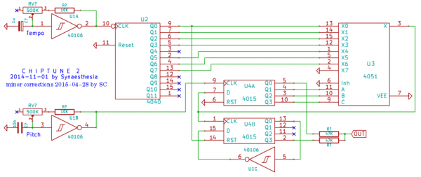
I have put together the Random ChipTune circuit on a breadboard since then, as well as the ChipTune 2 circuit after that. The Random ChipTune circuit uses both of the 4015's 4-stage serial-input / parallel-output shift registers, as does the ChipTune 2. I made some minor fixes to the ChipTune 2 schematic before I started to build it. These fixes reflect pin and chip numbering, so it would be easier for me to wire the circuit on the breadboard. I am a beginner, so I may have made some errors? However, the circuit is now working beautifully on the breadboards !!! Once again, Thank You very much for posting these circuits. I am having SO much fun with them !!!
| Description: |
|
| Filesize: |
92.33 KB |
| Viewed: |
654 Time(s) |
| This image has been reduced to fit the page. Click on it to enlarge. |
|
|
|
|
Back to top
|
|
|
synaesthesia
Joined: May 27, 2014
Posts: 291
Location: Germany
Audio files: 85
|
| Posted: Tue Apr 28, 2015 1:33 pm Post subject:
|
|
|
Oops, seems that I forgot to run the annotation in KiCAD before capturing the circuit image. That explains why the pin numbers were missing.
Regarding the hangs, you are right that some patterns may repeat for a while depending on the connections to the 4051.
However, it could also happen if the reset signal for the counter is not connected to ground, so you should check that. |
|
|
Back to top
|
|
|
SC
Joined: Apr 20, 2015
Posts: 10
Location: US
|
| Posted: Sun May 03, 2015 8:46 pm Post subject:
ChipTune Symphony |
|
|
| I just finished putting together the ChipTune Symphony circuit on breadboards, and it is the best one yet !!! The schematic you published is beautiful and easy to follow. Thank You !!! |
|
|
Back to top
|
|
|
SC
Joined: Apr 20, 2015
Posts: 10
Location: US
|
|
|
Back to top
|
|
|
SC
Joined: Apr 20, 2015
Posts: 10
Location: US
|
| Posted: Wed May 20, 2015 9:27 am Post subject:
chiptune circuits |
|
|
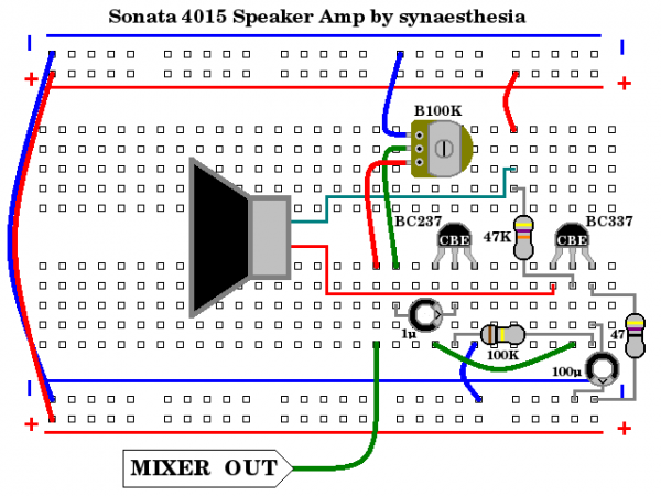
| I finished putting together the Sonata 4015 and the Opus 4053. Both of these are fun circuits to make and listen to. I have really enjoyed making these ChipTune Music Box circuits. One thing that made them so much fun was the wonderful schematics by synaesthesia. Thank you very much !!! ~SC |
|
|
Back to top
|
|
|
synaesthesia
Joined: May 27, 2014
Posts: 291
Location: Germany
Audio files: 85
|
| Posted: Wed May 20, 2015 1:08 pm Post subject:
|
|
|
| Thanks a lot for the nice feedback. I will keep posting more of these fun circuits. Right now I put myself a bit under pressure trying to complete several new things at once. There will be more soon. |
|
|
Back to top
|
|
|
SC
Joined: Apr 20, 2015
Posts: 10
Location: US
|
|
|
Back to top
|
|
|
synaesthesia
Joined: May 27, 2014
Posts: 291
Location: Germany
Audio files: 85
|
| Posted: Sun Aug 23, 2015 8:00 am Post subject:
|
|
|
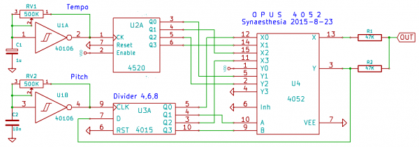
Here is one more chiptune circuit, this time using a 4052 instead of the 4051 to implement a shorter function table with just two variables. When using the Q1 and Q3 outputs of a 4015 to select from a four value function table and feeding the result back into the shift register, you get a variable divider by 4, 6, or 8, depending on the two inputs Y1 and Y2 of the 4052. Y0 must be Vdd and Y3 must be ground for the divider to work.
Now feed the two inputs Y1 and Y2 from two outputs of a 4520 counter and you have a base melody already at the Y output of the 4052. To make it a bit more interesting, I added a second voice. For that I feed the two unused outputs from the shift register and the two unused outputs from the counter to the other four X inputs of the 4052. Mix both, the X and Y outputs, with two resistors and you have a two voice melody that includes a bit of random variation.
You can change input A to the 4052 from Q1 to Q0 or Q2 of the 4015 to vary the scale. Also, try to swap the inputs to the 4052 around to change the melody, just keep Y0 at Vdd and Y3 at ground for the divider to work.
| Description: |
|
| Filesize: |
30 KB |
| Viewed: |
581 Time(s) |
| This image has been reduced to fit the page. Click on it to enlarge. |
|
| Description: |
|

Download |
| Filename: |
Opus4052.mp3 |
| Filesize: |
1.15 MB |
| Downloaded: |
886 Time(s) |
|
|
|
Back to top
|
|
|
PHOBoS

Joined: Jan 14, 2010
Posts: 5609
Location: Moon Base
Audio files: 705
|
| Posted: Tue Aug 25, 2015 5:56 am Post subject:
|
|
|
I like these circuits a lot, but the downside is that the only produce a limited melody. I wonder if there
is a way to incorporate some DIP switches, probably controlling muxes, to set different patterns.
Maybe add a digital counter somewhere that uses a prime number for some more variation.
hmm a VCO for the pitch oscillator might be interesting too (controlled by the circuit itself). Anyway keep it up! 
_________________
"My perf, it's full of holes!"
http://phobos.000space.com/
SoundCloud BandCamp MixCloud Stickney Synthyards Captain Collider Twitch YouTube |
|
|
Back to top
|
|
|
SC
Joined: Apr 20, 2015
Posts: 10
Location: US
|
Posted: Mon Sep 07, 2015 5:47 am Post subject:
 |
|
|
| Quote: | On Sun Aug 23, 2015 8:00 am synaesthesia wrote:
You can change input A to the 4052 from Q1 to Q0 or Q2 of the 4015 to vary the scale. Also, try to swap the inputs to the 4052 around to change the melody, just keep Y0 at Vdd and Y3 at ground for the divider to work. |
Thank you very much for posting this circuit. Your patch schematic is very easy to follow. I put this together on my ChipTune Music Box breadboard, and hooked the output up to a Ruby Amp by RunOffGroove attached to a 4 inch 8 Ohm speaker that I found at the Thrift store. These circuits are so much fun !!! I love them. ~SC |
|
|
Back to top
|
|
|
synaesthesia
Joined: May 27, 2014
Posts: 291
Location: Germany
Audio files: 85
|
|
|
Back to top
|
|
|
|

 Forum index » DIY Hardware and Software » Lunettas - circuits inspired by Stanley Lunetta