| Author |
Message |
NOISEBOB

Joined: Oct 13, 2019
Posts: 33
Location: NOISE
|
 Posted: Sat Oct 26, 2019 2:05 pm Post subject: Posted: Sat Oct 26, 2019 2:05 pm Post subject:
|
  |
|
| PHOBoS wrote: | yep, for 'beats' they work great, not so much for tuning.
As for the schematic,. what you've drawn would function as a standard oscillator since pin 1 of the NAND gate is high at all times.
Your input can't really do anything apart from shorting out the supply if the pot is at a very low resistance. You could add a resistor
between pin 1 and +9V in which case it could function as a gated oscillator and the pot might adjust the treshold level a bit.
It wouldn't NANDulate though. |
my idea with having a jack in on the first NAND gate is to be able to dignal in an output from the 2nd NAND, and give the input of that NAND a signal from the 3rd NAND, and so on....
and/or have the option of playing all four (or eight) oscillators individually. |
|
|
Back to top
|
|
 |
PHOBoS

Joined: Jan 14, 2010
Posts: 5911
Location: Moon Base
Audio files: 709
|
| Posted: Sat Oct 26, 2019 3:48 pm Post subject:
|
|
|
That would be a gated oscillator. I have some in my modular lunetta for which you can find the schematic here
In your case you can replace the switch with a (10K) pullup resistor and leave out the 100K pulldown. Then reverse the diode so it is facing
in the same direction as in your schematic. This way it will oscillate when nothing is plugged in and external signal can halt it (when low).
You could add a potentiometer as a voltage divider to the input but I doubt it would have any effect especially with those schmitt trigger inputs.
It could be useful for analog signals though.
_________________
"My perf, it's full of holes!"
http://phobos.000space.com/
SoundCloud BandCamp MixCloud Stickney Synthyards Captain Collider Twitch YouTube |
|
|
Back to top
|
|
|
GlassHausen

Joined: Nov 06, 2019
Posts: 6
Location: Portland, Oregon, USA
|
| Posted: Sun Mar 08, 2020 2:37 pm Post subject:
|
|
|
| My first day on the forums and already I've got three new projects to make! It's like finding a magical cave full of treasure! Thanks, PHOBos, for the original post, and thanks to everyone who has contributed. This stuff is amazing! |
|
|
Back to top
|
|
|
moosapotamus

Joined: May 11, 2007
Posts: 113
Location: New Hampshire USA
|
|
|
Back to top
|
|
|
PHOBoS
Joined: Jan 14, 2010
Posts: 5911
Location: Moon Base
Audio files: 709
|
| Posted: Tue Apr 04, 2023 1:31 pm Post subject:
|
|
|
welcome to the NANDulator club or cult or whatever this is, great to hear you're having fun with it 
Making it into a eurorack module did cross my mind but I felt that without any (analog) inputs it might not be that useful.
I did make a board for Muied Lumens with a couple of comparators that basically function as a 1bit ADC for use with analog signals.
Vactrols should give you some nice effects though considering that those oscillators can be fun with an LDR.
I have actually not tried any starving which can be very effective with CMOS.
As for the 'filter', yeah that's kinda what it sounds like to me too,.
I think it's actually somewhat controlling/modulating the pulsewidth
What do you use for the output circuitry ?
_________________
"My perf, it's full of holes!"
http://phobos.000space.com/
SoundCloud BandCamp MixCloud Stickney Synthyards Captain Collider Twitch YouTube |
|
|
Back to top
|
|
|
moosapotamus
Joined: May 11, 2007
Posts: 113
Location: New Hampshire USA
|
| Posted: Wed Apr 05, 2023 7:23 am Post subject:
|
|
|
| PHOBoS wrote: | | welcome to the NANDulator club or cult or whatever this is, great to hear you're having fun with it |
Thank you for sharing so many of your ideas here. Happy to join in the fun!
I used the output buffer as in the schematic that you posted with the 8x8 LED display. Not sure if 100K to the LED in each of the vactrols is the right value. I still need to sort that. But, my schematic is below. It doesn't show the 8x8 display, but it is absolutely included in the module.
Of course, would be happy to hear any additional feedback or thoughts on the plan shown in my schematic.
I have PCBs on order. Still need to order the 8x8 display, too. I'm assuming that this one will do the trick...
https://www.adafruit.com/product/1623
Thanks, again, for posting so much cool stuff here! Was working on a version of the Little Gate, but needed to order some parts and just got distracted! I'll be getting back to that asap, as long as I don't get distracted by some other shiny, noisy thing! 
| Description: |
|
| Filesize: |
65.9 KB |
| Viewed: |
294 Time(s) |
| This image has been reduced to fit the page. Click on it to enlarge. |
|
_________________
moosapotamus.net
"I tend to like anything that I think sounds good" |
|
|
Back to top
|
|
|
PHOBoS
Joined: Jan 14, 2010
Posts: 5911
Location: Moon Base
Audio files: 709
|
| Posted: Wed Apr 05, 2023 4:56 pm Post subject:
|
|
|
will have a look at the schematic but first,..
It is useful but does not have the same pinout.
It's a bit confusing with matrix displays labeled as common cathode or common anode. The LEDs are connected to eachother in the same way
(a matrix) it's just that the pins they connect to are flipped around.
I see I labeled the one I used as Row Anode (which I think is the same as Common Anode), the datasheet of the one on the sparkfun site
mentions that the KWM-30881CPGB is a Row Cathode display.
I think it would actually still work but is inverted and somewhat different and has a higher current draw.
_________________
"My perf, it's full of holes!"
http://phobos.000space.com/
SoundCloud BandCamp MixCloud Stickney Synthyards Captain Collider Twitch YouTube |
|
|
Back to top
|
|
|
moosapotamus
Joined: May 11, 2007
Posts: 113
Location: New Hampshire USA
|
| Posted: Thu Apr 06, 2023 10:13 am Post subject:
|
|
|
| PHOBoS wrote: | will have a look at the schematic but first,..
It is useful but does not have the same pinout... |
Hrmmm... Thanks! Glad I asked. So, if I have a Row Cathode matrix like that adafruit one, might I just need to flip it around? And then the patterns in the display might just move in a different (opposite?) direction? I suppose I can live with slightly higher current draw. But would I maybe need to change the value of those 1k resistors?
I see that Tayda appears to have the 32mm Row Anode matrices in red.
https://www.taydaelectronics.com/8x8-dot-matrix-led-display-red-3mm.html
Do you have a link to the source for the 8x8 display that you used?
_________________
moosapotamus.net
"I tend to like anything that I think sounds good" |
|
|
Back to top
|
|
|
PHOBoS
Joined: Jan 14, 2010
Posts: 5911
Location: Moon Base
Audio files: 709
|
| Posted: Thu Apr 06, 2023 3:57 pm Post subject:
|
|
|
| Quote: | | Hrmmm... Thanks! Glad I asked. So, if I have a Row Cathode matrix like that adafruit one, might I just need to flip it around? And then the patterns in the display might just move in a different (opposite?) direction? I suppose I can live with slightly higher current draw. But would I maybe need to change the value of those 1k resistors? |
not exactly
The pinout is not nicely split in anode pins on one side and cathode pins on the other side,
It's pretty jumbled up and there doesn't seem to be any rhyme or reason to the order. (it does appear to be some sort of standard layout though)
Could be interesting to see what happens if you do flip it around but it will probably not make much sense.
If you use a row cathode display instead of a row anode display it is also not exactly inverted but close to it.
Both 4017 counters have only 1 active (high) output, one of them controls 1 row of anodes directly, the other one is inverted
and controls 1 column of cathodes. Where this active row and column meet 1 LED lights up. With this setup only 1 LED can be on
at any given time but because of the high frequencies it will appear that multiple are on. At least if you use a row anode display.
With a row cathode display the not active (low) outputs of the 4017's will now turn the LEDs on. The result would be that only 1 row and
1 column will be off resulting in 49 LEDs to be on at any given time. In theory the current would be about 7x as high because the LEDs
are wired in a matrix resulting in 7 LEDs wired in parallel per 1K resistor.
I don't know if they still sell the exact same one but I got mine from Tayda as well.
_________________
"My perf, it's full of holes!"
http://phobos.000space.com/
SoundCloud BandCamp MixCloud Stickney Synthyards Captain Collider Twitch YouTube |
|
|
Back to top
|
|
|
moosapotamus
Joined: May 11, 2007
Posts: 113
Location: New Hampshire USA
|
|
|
Back to top
|
|
|
PHOBoS
Joined: Jan 14, 2010
Posts: 5911
Location: Moon Base
Audio files: 709
|
| Posted: Wed Apr 12, 2023 5:07 pm Post subject:
|
|
|
that looks very nice. 
appears larger than it is. knowing that it's eurorack.
| Quote: | | I need to cut out the square opening for the matrix myself. |
hmm, it's not the worst material to work with but I hope that works out ok.
I did have a look at the schematic and nothing stands out as being wrong. I like how you shared the capacitors on the switches.
The output level might be a bit low for modular since it is designed as a line level output but you can easily boost it by reducing R9.
Not sure how the starve will work out with the display. If you are also starving that then it will affect the sound which could be
interesting but it could also limit the starve range. If you are not starving it then the 4017s might not get triggered properly anymore
beyond a certain point.
_________________
"My perf, it's full of holes!"
http://phobos.000space.com/
SoundCloud BandCamp MixCloud Stickney Synthyards Captain Collider Twitch YouTube |
|
|
Back to top
|
|
|
moosapotamus
Joined: May 11, 2007
Posts: 113
Location: New Hampshire USA
|
| Posted: Fri Apr 14, 2023 8:04 am Post subject:
|
|
|
Cutting out the square opening for the matrix shouldn't be too terribly tough. Maybe I'm being optimistic, but having a nice silkscreen line to follow (as opposed to laying it out myself) helps a lot. I also have to drill out a few of the holes as the max diam that jlcpcb will do is 6.3mm.
Thanks for looking through my schematic! Well, it is mostly your design, anyway. Happy to send you a set of boards if you like (PM me). Although, based on your comments about the Starve control, understand if you'd rather wait and see/hear how v1.0 comes out. Just received the last of the needed parts. So, shouldn't be too long...
In this layout, I am only starving the 4093. It didn't occur to me that the 4017s might not get triggered enough to feed the display. Makes sense. Guess I'll have to just see what happens. I didn't have any displays when I breadboarded. Thought that part seemed relatively straightforward. Silly me!
OTOH, I don't quite see how starving the display (the 4017s) would have it's own affect on the sound. I had thought that would just cause the display to conk out, which is why I chose not to do it that way.
_________________
moosapotamus.net
"I tend to like anything that I think sounds good" |
|
|
Back to top
|
|
|
PHOBoS
Joined: Jan 14, 2010
Posts: 5911
Location: Moon Base
Audio files: 709
|
| Posted: Fri Apr 14, 2023 1:01 pm Post subject:
|
|
|
| moosapotamus wrote: | | I also have to drill out a few of the holes as the max diam that jlcpcb will do is 6.3mm. |
It should be possible to have larger holes but you probably have to make it a milling layer instead of drilling.
That's also how you could get the square hole to be cut out. The 6.3 might be the limit for hole metallization though.
| Quote: | | OTOH, I don't quite see how starving the display (the 4017s) would have it's own affect on the sound. I had thought that would just cause the display to conk out, which is why I chose not to do it that way. |
Everything that requires current will have an effect when you limit the current.
At some point the display would indeed just stop working properly but it is possible that at that point
the rest of the circuit isn't producing anything useful anymore anyway.
Power starving is very experimental in that regard but that's also what can make it very interesting.
_________________
"My perf, it's full of holes!"
http://phobos.000space.com/
SoundCloud BandCamp MixCloud Stickney Synthyards Captain Collider Twitch YouTube |
|
|
Back to top
|
|
|
moosapotamus
Joined: May 11, 2007
Posts: 113
Location: New Hampshire USA
|
|
|
Back to top
|
|
|
moosapotamus
Joined: May 11, 2007
Posts: 113
Location: New Hampshire USA
|
| Posted: Thu Apr 20, 2023 2:41 pm Post subject:
|
|
|
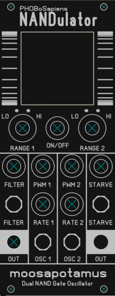
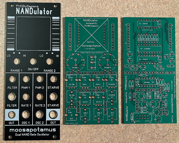
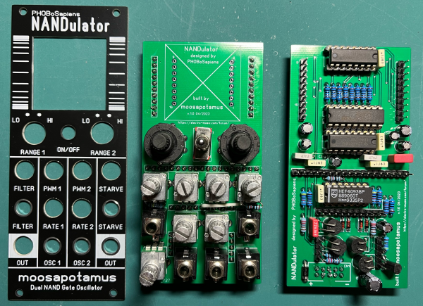
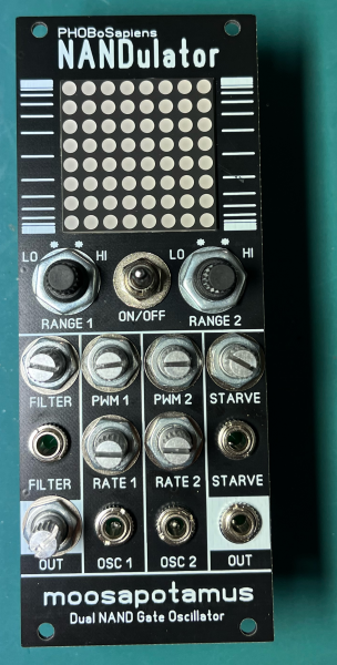
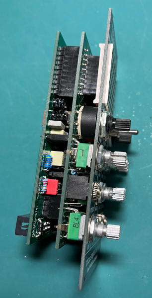
Here are some picks of how all the bits came out. Cutting out the square for the matrix was a little tricky. Honestly, I was a little too gung ho at the start and ruined one panel. But I took my time with the second and I'm relatively happy with how it came out. Just one minor blemish on the face.
I haven't picked out knobs, yet. Given the 10hp size, it's a little tight and the knurled shafts, while not being particularly attractive, I think allow for easier control. But the rotary range switches, at least, could probably use some knobs.
Getting some modulation from the Starve and Filter inputs, now. Turning Starve up all the way does eventually blank out the display, but doesn't necessarily mute the output. Starve also causes the output volume to drop. So, the volume control is quite useful. And the Starve control is a nice add-on.
The range switches are also a lot of fun to play with. I could stare at the display and doodle with this for hours! I'll post some better audio/video when I have a bit more time.
| Description: |
|
| Filesize: |
9.33 MB |
| Viewed: |
276 Time(s) |
| This image has been reduced to fit the page. Click on it to enlarge. |
|
| Description: |
|
| Filesize: |
4.49 MB |
| Viewed: |
259 Time(s) |
| This image has been reduced to fit the page. Click on it to enlarge. |
|
| Description: |
|
| Filesize: |
6 MB |
| Viewed: |
245 Time(s) |
| This image has been reduced to fit the page. Click on it to enlarge. |
|
_________________
moosapotamus.net
"I tend to like anything that I think sounds good" |
|
|
Back to top
|
|
|
PHOBoS
Joined: Jan 14, 2010
Posts: 5911
Location: Moon Base
Audio files: 709
|
|
|
Back to top
|
|
|
moosapotamus
Joined: May 11, 2007
Posts: 113
Location: New Hampshire USA
|
| Posted: Sun Apr 23, 2023 8:46 am Post subject:
|
|
|
| PHOBoS wrote: | That came out looking great!
Good to see you are using an "approved" HEF4093  |
Thanks! Yes, I did have some 'inferior' 4093s, but made a point of finding the premium variety.
| Quote: | I was curious what kind of range switches you'd be using as I couldn't really make it out from the footprint.
Don't think I had seen those small rotary switches before. |
I think they come from adafruit, but I bought them on ebay. They come in both sp8t and 2p4t and are definitely smaller than the bulky Greyhill rotaries. However, you cannot adjust the number of throws as you can with the Greyhill. You are stuck with either 4 position or 8 position, depending on which config you get. But the compact size outweighs that minor drawback for me. The 8 position (sp8t) rotate continuously around, like an encoder.
https://www.adafruit.com/product/2925
https://www.pedalpcb.com/product/mini-rotary-switch-2p4t/
For the knurled shaft pots, I might try those tall trimmer toppers. I've had the micro knobs and found them too smooth, no grip. At least the trimmer toppers look knurled/serrated for slightly better grip. I can see how bare knurled shafts can be rough on the fingertips after a while.
I just put a pair of these on the rotary switches...
https://lovemyswitches.com/rubber-knob-knurled-shaft-the-larry-14mm-od/
...just because I happened to already have them on hand. Not too bad looking. They might stay. Combined with black tall trimmer toppers could be the answer.
Next build, to go with the NANDulator, will probably be an Envelope/VCA. Been eyeballing the Ian Fritz AD/AR generator and thinking of combining it with a LM13700 base VCA. Since two VCAs can be had with one LM13700, probably make it a dual ENV/VCA unit.
Thanks, again, for sharing your NANDulator!
_________________
moosapotamus.net
"I tend to like anything that I think sounds good" |
|
|
Back to top
|
|
|
|

 Forum index » DIY Hardware and Software » Lunettas - circuits inspired by Stanley Lunetta