| Author |
Message |
rhdf
Joined: Jul 11, 2014
Posts: 39
Location: Sweden
|
 Posted: Wed May 18, 2016 3:18 pm Post subject:
Modified ADSR Posted: Wed May 18, 2016 3:18 pm Post subject:
Modified ADSR |
  |
|
Hi
In the "2016 builds" thread I saw AlanP:s 4HP version of the ADSR v2 (http://electro-music.com/forum/post-419273.html#419273) and thought: "Is it possible to make a single board version with all features on"
Answer is Yes, with SMD and 9mm pots 
Then I started scratching my head a bit, and realized that the Mini/Microbrute uses more or less the same circuit.
Differences are that the OP-amp buffer between Sustain and Decay are replaced by a mosfet and there are no inverted output, manual gate or switch for slow/fast
Another difference is that the micro uses 10k Log pots instead of 1M. I did some simulations with 100k because I noticed that 9mm 1M log was harder to source (especially with D-shafts)
Any downsides to build a bastard of the original V2 and the micro version?
One thing I haven't figured out is why there is a 10k resistor on on side of the gate-button and a 47k on the other, (R4 and R5) in the original scheme. A single resistor of 57k would seem to do the same thing. Or? |
|
|
Back to top
|
|
 |
AlanP
Joined: Mar 11, 2014
Posts: 746
Location: New Zealand
Audio files: 41
|
| Posted: Wed May 18, 2016 7:19 pm Post subject:
Re: Modified ADSR |
|
|
| rhdf wrote: | | Any downsides to build a bastard of the original V2 and the micro version? |
Give it a go and find out troubleshooting... you get such a good feeling once it's over! |
|
|
Back to top
|
|
|
Grumble

Joined: Nov 23, 2015
Posts: 1310
Location: Netherlands
Audio files: 30
|
| Posted: Thu May 19, 2016 12:04 am Post subject:
Re: Modified ADSR |
|
|
| rhdf wrote: | Hi
One thing I haven't figured out is why there is a 10k resistor on on side of the gate-button and a 47k on the other, (R4 and R5) in the original scheme. A single resistor of 57k would seem to do the same thing. Or? |
You are right into thinking that one resistor of 57k acts the same as two resistors with a combined value of 57k.
I think it is done to prevent a psu shortage if one of the connections of the switch is shorted to ground.
It is common practice to have a resistor between the power supply and a wire going to a connector/switch/whathaveyou.
The same is done with R12 going to P4.
If you make a single board version with no wiring, the resistors R4 and R5 can be replaced by one resistor of 56k (E12 series).
 |
|
|
Back to top
|
|
|
rhdf
Joined: Jul 11, 2014
Posts: 39
Location: Sweden
|
| Posted: Thu May 19, 2016 2:10 am Post subject:
|
|
|
It seems that a euro-version of the microbrute ADSR is where this going to end up in.
Well, with the addition of a inverted out, gate-button and slow/fast switch
Mods so far:
Adjusted R3 to 2,2M
Mosfet between pin 7 of the 7555 and Sustain-pot (Removed U2d)
Replaced the led-driver with a transistor (same as in the micro/mini)
This results in some extra passives, but I can use a TL0X2 instead
Now some test of what happens if I move the treshhold from the output of U2a to the + in and changed values of the pots.
I Realize that it probably no longer going to behave as the original v2, but its still a adsr |
|
|
Back to top
|
|
|
rhdf
Joined: Jul 11, 2014
Posts: 39
Location: Sweden
|
| Posted: Thu May 26, 2016 4:27 pm Post subject:
|
|
|
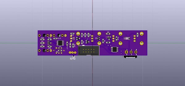
After a couple of hours of moving stuff around and reading datasheets I finally have managed to get almost everything to fit on a 25x109mm PCB, (with some margins to the edges)
When reading the datasheet for ICM7555 I noticed that pin 5 (Control) don't need a decoupling cap is it OK to leave it out, or at least put a ceramic 10nf instead of a "big" film-cap?
And another question:
I was first planning to have at least pads for the optional R17 and a small switch (easy to change range instead of having to solder on/off a resistor)
Thinking of it twice: Do I really need it? According to the "euro-standard" negative Envelopes goes from 0 to -8V |
|
|
Back to top
|
|
|
roglok

Joined: Aug 28, 2010
Posts: 202
Location: uptown
|
| Posted: Fri May 27, 2016 12:57 am Post subject:
|
|
|
| rhdf wrote: |
And another question:
I was first planning to have at least pads for the optional R17 and a small switch (easy to change range instead of having to solder on/off a resistor)
Thinking of it twice: Do I really need it? According to the "euro-standard" negative Envelopes goes from 0 to -8V |
i have done it that way (switchable neg/pos inverted envelope) and find it quite handy. while you may not use it in every patch i'd still include pads on the pcb for the switch. to my knowledge there is no "euro-standard", so i'd feel free to do whatever makes sense. |
|
|
Back to top
|
|
|
AlanP
Joined: Mar 11, 2014
Posts: 746
Location: New Zealand
Audio files: 41
|
| Posted: Fri May 27, 2016 3:01 am Post subject:
|
|
|
| The only real standard is the mounting and voltage rails. |
|
|
Back to top
|
|
|
rhdf
Joined: Jul 11, 2014
Posts: 39
Location: Sweden
|
|
|
Back to top
|
|
|
AlanP
Joined: Mar 11, 2014
Posts: 746
Location: New Zealand
Audio files: 41
|
| Posted: Sun May 29, 2016 2:53 pm Post subject:
|
|
|
| rhdf wrote: | | A solution for no1 would be to have a slide switch accessible from the front, but squeeze that in on a 6HP panel is a challenge in it self |
Another option is header pins on the back, with a jumper -- I did this to select fast/slow, with my adsr layout. |
|
|
Back to top
|
|
|
rhdf
Joined: Jul 11, 2014
Posts: 39
Location: Sweden
|
| Posted: Mon May 30, 2016 8:00 am Post subject:
|
|
|
| AlanP wrote: |
Another option is header pins on the back |
I've found small switches with .1 inch legspacing, so its possible to put in a header instead.
That is, if I not decide to only have 0 to -8V. I can see me scratching my head why something doesn't do as expected just because I forgotten witch ADSR has the 8-0V mode
Next version might get a panel-switch for it (and a bright red LED  ) ) |
|
|
Back to top
|
|
|
|

 Forum index » DIY Hardware and Software » YuSynth