| Author |
Message |
Cfish

Joined: Feb 24, 2016
Posts: 477
Location: Indiana
|
 Posted: Sat Dec 31, 2016 8:47 pm Post subject: Posted: Sat Dec 31, 2016 8:47 pm Post subject:
|
  |
|
I had never really read through this thread.
My LFOs in my synth are my own design and swing +14 to -14 at max setting.
I initially had a problem with them redgestering on the VCO, even though my power supplier is not close to being loaded heavy.
I have a 1.5 amp supply in each rack. Max I have tested is .78 amp
I added 3500 uf caps on each supply line to ground at the LFOs and cleared the problem right up.
I started adding extra capicitors on the power input of all my modules, at least 100uf per module higher on things like my sequencer and don't seem to have the problems anymore. |
|
|
Back to top
|
|
 |
alanwilder81
Joined: Sep 03, 2016
Posts: 310
Location: italy
|
| Posted: Sun Jan 01, 2017 9:13 am Post subject:
|
|
|
hello Cfish,thanks for you precious contribution.Adding massive capacitors to the LFO circuitry may be the cure to the problem.
What do you mean by "redgestering on the VCO" ? i searched on the net for translation but i couldnt find the word 
However, what it still puzzles me, is the fact that both you and the guy who started this thread, experimented VCO misbehaviours although the PSU was far from being overloaded.
1.5 A is a hell of a current supply for a "basic" synth setup,more than enough i seem to grasp. Yet it crapped out in both of your cases cases. 
And even i run through the same crap having an extremely simple LFO and VCO powered to the same PSU .it's rated at 0.250 mA, small all you like but probably up to the job.
Simply put, the VCO pitch started to wobble without even connecting the LFO output to the VCO. |
|
|
Back to top
|
|
|
Cfish
Joined: Feb 24, 2016
Posts: 477
Location: Indiana
|
| Posted: Sun Jan 01, 2017 9:42 am Post subject:
|
|
|
[quote="alanwilder81"]
What do you mean by "redgestering on the VCO" ?
That the LFO was affecting the VCO even when it was not plugged in to it.
Was not a lot. But it was there.
Power supplies sometimes can't react fast enough to current changes, even if the supply is big enough.
The capicitors in the supply are trying to correct and balance changes in voltage due to changes in current draw.
Capicitors at each module help lighten that load on the power supply capicitors.
That's why Thomas Henrey always has capicitors at the power input of his schematics. VCO 1 has several 10uf capicitors at its power input.
If you leave them out, bleed over is much more noticeable. |
|
|
Back to top
|
|
|
alanwilder81
Joined: Sep 03, 2016
Posts: 310
Location: italy
|
| Posted: Sun Jan 01, 2017 10:12 am Post subject:
|
|
|
thanks Cfish,
it makes more sense now! 
it surprises me that power supplies sometimes can't react fast enough to current changes, even if the supply is big enough.
But hey, given that capacitors at each module help lighten that load on the power supply capacitors, i will install them to fix the problem.
It's a nice trick to learn ! |
|
|
Back to top
|
|
|
wackelpeter
Joined: May 05, 2013
Posts: 461
Location: germany
Audio files: 10
|
| Posted: Sun Jan 01, 2017 10:16 am Post subject:
|
|
|
10, 22 or even 47uF is something different as having Minimum 100uF or even 3500uF caps at the power lines for each module would say...
I believe there is a reason why Thomas Henry, Ian Fritz, to name few, stick to those smaller caps and didn't use those big caps always, away from the financial part, because they are higher in price.
Those caps with the assigned and mostly recommended resistor (10-22R) or ferrite bead form also a RC-filter at the supply, to keep noise Distribution over the power rails minimal...
If only one LFO is affecting your VCO there are other things i would look for.
First of all stabilize the PSU to it's best, secondly check the current consumption and also check the wiring of my modules... eventually keeping them in bigger distance from each other when going to the panels, using shielded wires and so on... Square, pulse or saw waves (or other forms with a hard falling or rising edge) and noise above a certain level can spread parasitic into other wires in near distance, especially if they're Close together and share some greater distance the same way, when not shielded...
As i said before measure the current consumption with only the VCO then plug in the LFO too and measure again... see what is the difference between the minimum and maximum current draw'n out of your PSU with the LFO
As you said your PSU is rated 250mA i would not use it to it's upper edge as it's not unlikely taht it will become unstable and whacky...
Also might add that non-propper grounding could be an issue for such Things sometimes as well... and furhter as we're speaking of caps at the power rails, don't forget to add bypass caps to the power Inputs at each IC as close as possible to their designators...
_________________
https://soundcloud.com/bastian-j |
|
|
Back to top
|
|
|
Cfish
Joined: Feb 24, 2016
Posts: 477
Location: Indiana
|
| Posted: Sun Jan 01, 2017 10:57 am Post subject:
|
|
|
Here is a great link to what Wackelpeter was talking about. (Using multiple small caps, instead of one large cap)
Is a great video PhoBos put a link to it on one of my threads to help me out.
https://youtu.be/BcJ6UdDx1vg
Last edited by Cfish on Sun Jan 01, 2017 11:02 am; edited 1 time in total |
|
|
Back to top
|
|
|
alanwilder81
Joined: Sep 03, 2016
Posts: 310
Location: italy
|
| Posted: Sun Jan 01, 2017 11:01 am Post subject:
|
|
|
hello wackelpeter.Again thanks for the in depth and detailed analysis. The vast amount of parameters and variables you add to the equation never cease to amaze me.
Golden tips there regarding the RC LPF formed by resistors plus caps to clear up noise signals.
I am just about to build a PSU from scratch. believe am going for the Thomas Henry design.
So am i better stick to those low caps values the big synth designers recommend? |
|
|
Back to top
|
|
|
wackelpeter
Joined: May 05, 2013
Posts: 461
Location: germany
Audio files: 10
|
| Posted: Sun Jan 01, 2017 11:34 am Post subject:
|
|
|
Sorry if i was a bit unclear.
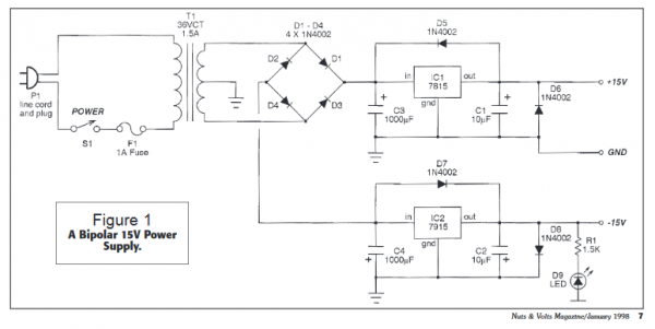
The really big caps (1000uF and more) you use on your PSU before the regulators... also recommended is that you use before and after the Regulator a 1-10uF tantalum cap as close to the in- and output as possible...
Then you use 10-22uF or for some critical devices maybe 47uF at the point where the cables from the PSU enter the board... and then you spread all those 100nF caps (ceramic is good enough for that) around the IC's close to their power Inputs connecting them between V+ and gnd and V- and gnd... or in single supply variants such as CMOS chips simply between V+ and gnd
...and btw. don't take all my words too seriously as i'm not a electronic engineer nor do i have the knowledge... i'm just repeating what i have snapped of in the forums here, keeping my fingers crossed that i hopefully don't mix up things.
But as CFish mentioned just putting those 3500uF caps in instead of 22uF or something like that seems to me more like doctoring around the Symptoms rather then curing an possible mistake... When you need so much caps to Keep things stable then i would say ii isn't unlikely there's something wrong in this circuit and heavily affecting the PSU's stability... so i would look therefore first...
_________________
https://soundcloud.com/bastian-j |
|
|
Back to top
|
|
|
alanwilder81
Joined: Sep 03, 2016
Posts: 310
Location: italy
|
|
|
Back to top
|
|
|
wackelpeter
Joined: May 05, 2013
Posts: 461
Location: germany
Audio files: 10
|
| Posted: Sun Jan 01, 2017 12:25 pm Post subject:
|
|
|
The only basic knowledge i have is from what is left from my school days some 25 years ago and those things i learned from debugging and fixing my own builds... so not the most reliable source i would say... but i do hopefully hint often enough that may answers shouldn't be mistaken as those by someone knows what's going on inside the circuits... because i mostly can't figure this out... there are plenty others here which are a hell better in that and they have definitely more knowledge of what is going on inside... 
Well that PSU from Thomas should be great for DIYlers and the synth builders but i would have some slight scruples to recommend such PSU's involving 230V mains power for beginners or unexperienced persons...
It's still dangerous and can be lethal... So i would maybe recommend to start off with a wallwart PSU...
And when it must be a 230V powered PSU then better stick to an DIY PCB Kit that is tested and proven to be safe instead of trying to design a PCB Board yourself...
_________________
https://soundcloud.com/bastian-j |
|
|
Back to top
|
|
|
alanwilder81
Joined: Sep 03, 2016
Posts: 310
Location: italy
|
| Posted: Sun Jan 01, 2017 1:05 pm Post subject:
|
|
|
sure wackelpeter
its never a good thing to fuck around with high voltages . Luckily, i got in touch with a local italian EE professor who's willingly gonna do the dangerous part of the job for me.
Like getting the right transformer and fuses, doing the proper earthing and casing etc etc.
I definitely would never ever venture to build such circuit.
I was just weighing the best PSU options available.Once i get a clearer mind of what's best for my modular project, i'll get the professor the circuit to implement  |
|
|
Back to top
|
|
|
Cfish
Joined: Feb 24, 2016
Posts: 477
Location: Indiana
|
|
|
Back to top
|
|
|
alanwilder81
Joined: Sep 03, 2016
Posts: 310
Location: italy
|
| Posted: Sun Jan 01, 2017 2:49 pm Post subject:
|
|
|
thanks Cfish
it looks awesomely good to purchase pre made PSU's from e bay. Sure convenience is there,but i'd love to learn the old way,that of the analog days when every and each one built their own custom PSU.
Or have it built by someone else lol 
anyway, i'll give it a go, because it's handy to have a second PSU for sure |
|
|
Back to top
|
|
|
Cfish
Joined: Feb 24, 2016
Posts: 477
Location: Indiana
|
| Posted: Sun Jan 01, 2017 3:02 pm Post subject:
|
|
|
I agree alanwilder81. I built a couple before I started buying them.
Make sure you use high quality diodes from a good supplier.
I popped about 30 dollars worth of capicitors once over cheep, ordered from china, diodes.
If you need to find a transformer, there is a place called Andies arcade out of California online.
I guess vintage console arcade games used a lot of 15v+-
I think they still have them in 240v primary. |
|
|
Back to top
|
|
|
alanwilder81
Joined: Sep 03, 2016
Posts: 310
Location: italy
|
| Posted: Sun Jan 01, 2017 3:08 pm Post subject:
|
|
|
great Cfish !
i have a load of 1n4007 diodes, a hell of a lot of bridge rectifiers, fuses, and electrolitic capacitors. They have been sitting there for quite long i suppose,sort of old stock stuff. All in mnt condtion.
The transformer is the only thing i need, still looking around.
|
|
|
Back to top
|
|
|
alanwilder81
Joined: Sep 03, 2016
Posts: 310
Location: italy
|
| Posted: Sun Jan 01, 2017 3:10 pm Post subject:
|
|
|
| that stuff comes from different reputable suppliers thankfully.no chinese capacitors, i ve heard bad stories about them |
|
|
Back to top
|
|
|
micromusic
Joined: May 05, 2014
Posts: 61
Location: england
|
| Posted: Sat Jan 21, 2017 4:23 pm Post subject:
|
|
|
| For power supply build the Digisound one its simple and works |
|
|
Back to top
|
|
|
gabbagabi

Joined: Nov 29, 2008
Posts: 652
Location: Berlin by n8
Audio files: 23
|
| Posted: Wed Jan 25, 2017 11:38 am Post subject:
|
|
|
some things,
the 79xx needs always a minimal load, eg LED, otherwise u will meassure something unexpected.
my experience is that it is hard to find equal 79xx and 78xx, means u have later a PSU with eg. +14,87V and -14,69V.
it should be easier to "match" 78xx. You can build then two identical positive PSU and put them thogether as bipolar - the tranformers are also easier to source.
Regarding LEDs: dont drive them directly with a OPA use a transistor to drive them, cos a normal OPA can only drive around 25mA
other thing: if u want to limit the rectangle osc out from 15V to 5V dont go to low with the resistors for the same reason (had bad experience with 2K+1K)
regarding the 10R resistors on the power input, they are also a nice fuse, 16mA @15V i guess
cheers bb |
|
|
Back to top
|
|
|
|

 Forum index » DIY Hardware and Software » YuSynth