| Author |
Message |
mfsp
Joined: Mar 24, 2017
Posts: 5
Location: Germany
|
 Posted: Sun Nov 26, 2017 1:12 pm Post subject:
LFO 2 no triangle or sine waves Posted: Sun Nov 26, 2017 1:12 pm Post subject:
LFO 2 no triangle or sine waves |
  |
|
Hello everyone,
I'm trying to build one LFO 2 but I'm experiencing some issues.
Since I had no triangle and sine waves, and after reading some of the topics related with the LFO's, I've decided to measure the resistors values and I've found that some of them are "burned" - the original values have decreased a lot.
R27 should be 22K now 19.38K
R12 should be 27K now 23.60K
R22 should be 49.9K now 30.70K
all of these should be 100K
but now they are
R11 58.6K
R9 58.5K
R20 66.2K
R19 66.4K
R21 65.9K
R24 R26 both should be 150K now 107K
R23 should be 200K now 125K
Any ideas of what might be causing this?
Thank you in advance,
Marco |
|
|
Back to top
|
|
 |
Grumble

Joined: Nov 23, 2015
Posts: 1320
Location: Netherlands
Audio files: 30
|
| Posted: Mon Nov 27, 2017 12:31 am Post subject:
|
|
|
Did you measure these values while the resistors where in the circuit?
Because if you measure resistances or capacitors "in situ" their values will be influenced by the components connected to them.
_________________
my synth |
|
|
Back to top
|
|
|
mfsp
Joined: Mar 24, 2017
Posts: 5
Location: Germany
|
| Posted: Mon Nov 27, 2017 5:11 am Post subject:
|
|
|
Hello,
Thank you so much for your answer.
Do you mean this much? Is it possible? |
|
|
Back to top
|
|
|
Grumble
Joined: Nov 23, 2015
Posts: 1320
Location: Netherlands
Audio files: 30
|
| Posted: Mon Nov 27, 2017 5:20 am Post subject:
|
|
|
I don't have the schematics of this LFO, but i'm sure it is not just possible that these values vary that much, but even very likely!
You might even discover that there will be a difference between the resistor values if you switch the test leads of your multi-meter caused by the internals of opamps or transistors.
_________________
my synth |
|
|
Back to top
|
|
|
Boerge

Joined: Sep 02, 2009
Posts: 82
Location: Germany
|
| Posted: Tue Nov 28, 2017 12:15 am Post subject:
|
|
|
First of all: I assume, you built this one:
http://yusynth.net/Modular/EN/LFO/VC-LFO2.html
No tri, no sine means: you have rectangles and saw? That would proof, that your LFO generally works. So, your measuring could be wrong (never measure resistors in the circuit unless you are able to calculate roughly the influence of the circuit!).
I would check the tri/sine converter parts, IC3b/c/d, specially the orientation of the diodes (if you used the 1N4148 the ring is the cathode). Check the inputs and the outputs of IC3b-d with a scope. I'm quite sure, that your problem lies somewhere in that part of the circuit.
regards
Boerge
_________________
...ich will doch nur löten... |
|
|
Back to top
|
|
|
mfsp
Joined: Mar 24, 2017
Posts: 5
Location: Germany
|
| Posted: Tue Nov 28, 2017 12:24 am Post subject:
|
|
|
Hello,
Thank you for your replies.
I've just checked and I can confirm that this values were indeed altered by the other components. Removed from the circuit, the values are as they should.
Back to square one  Why are there no triangle and sine waves? Why are there no triangle and sine waves?
Correct that's the one I'm trying to build. Yes, I have saw and pulse. I've changed both TL074 and still no good. I have the 1N4148's as seen here

Accepting the suggestion: testing, testing
Thank you,
Marco |
|
|
Back to top
|
|
|
Boerge
Joined: Sep 02, 2009
Posts: 82
Location: Germany
|
| Posted: Tue Nov 28, 2017 12:38 am Post subject:
|
|
|
Additional question: in what position is the trimmer T3 (Sine/Tri symmetry)? Always start with middle position of all trimmers! The trimmer should not have that big influence to prevent the circuit from working, but if R10 is to small, it could happen.
_________________
...ich will doch nur löten... |
|
|
Back to top
|
|
|
mfsp
Joined: Mar 24, 2017
Posts: 5
Location: Germany
|
| Posted: Tue Nov 28, 2017 12:47 am Post subject:
|
|
|
I didn't know that 
That's something worth trying. Thank you. |
|
|
Back to top
|
|
|
mfsp
Joined: Mar 24, 2017
Posts: 5
Location: Germany
|
| Posted: Wed Nov 29, 2017 6:18 am Post subject:
|
|
|
Hello,
Unfortunately I have to wait before proceeding with further tests. Yesterday I was using my oscilloscope and it started to smell like burned electronics 
I will be back with additional info regarding the lfo as soon as possible
Thank you,
Marco |
|
|
Back to top
|
|
|
RyBowk
Joined: Nov 25, 2018
Posts: 33
Location: England
|
| Posted: Sat Nov 16, 2019 6:56 am Post subject:
Triangle = saw |
|
|
Hi there, was there ever a solution to this problem? As I have a similar issue in that the triangle is a uniform saw which also resultis in a weird sine. I have a good saw and square, so that would leave me thinking that it’s somewhere within the triangle wave shaping that the problem lies. I have changed every ic every transistor, all caps several resistors. Also t2a and b have no effect on the circuit what so ever and I have also changed those. Oh and also I have changed the four diodes. Also the duty cycle of the pulse starts at 70%.
Thanks for any help, Ryan |
|
|
Back to top
|
|
|
gabbagabi

Joined: Nov 29, 2008
Posts: 652
Location: Berlin by n8
Audio files: 23
|
| Posted: Mon Nov 18, 2019 9:42 am Post subject:
|
|
|
| i can remember that ive forgot to solder in one of the brigdes, this was causing a strange sine |
|
|
Back to top
|
|
|
RyBowk
Joined: Nov 25, 2018
Posts: 33
Location: England
|
| Posted: Mon Nov 18, 2019 9:51 am Post subject:
|
|
|
Thanks for the reply. I am using a Soundtronics pcb that has two layers so there is no need to solder the bridges. I have tried everything I can think of. Funny thing is that the vco uses an almost identical saw to triangle wave shaper, and it seems to work fine. I’m at a loss.
Also the saw bias trimmers don’t seem to have any affect on the circuit whatsoever, I have tried changing them in case they were faulty but to no avail. |
|
|
Back to top
|
|
|
gabbagabi
Joined: Nov 29, 2008
Posts: 652
Location: Berlin by n8
Audio files: 23
|
| Posted: Mon Nov 18, 2019 11:04 am Post subject:
|
|
|
well just fishing around:
measure the outta pins of the saw offset trimmers, one pin should have 0V and the other about 10V, if pots/trimmers have no effect often one side is not connected
if you have a good saw, where do u measure it? what is the amplitude?
note also that in yves schematic is an error, R17 (200k) exist two times, but one should be 100k (ic2a in the schemo) |
|
|
Back to top
|
|
|
RyBowk
Joined: Nov 25, 2018
Posts: 33
Location: England
|
| Posted: Mon Nov 18, 2019 1:44 pm Post subject:
|
|
|
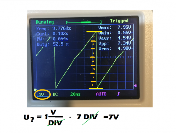
Here is a (cheap) scope image from pin 14 of ic 2, same reading as pin 7.
I’m only getting 20% of the duty cycle of the pulse too.
| Description: |
|
| Filesize: |
2.13 MB |
| Viewed: |
326 Time(s) |
| This image has been reduced to fit the page. Click on it to enlarge. |

|
| Description: |
|
| Filesize: |
2.13 MB |
| Viewed: |
289 Time(s) |
| This image has been reduced to fit the page. Click on it to enlarge. |

|
|
|
|
Back to top
|
|
|
RyBowk
Joined: Nov 25, 2018
Posts: 33
Location: England
|
| Posted: Mon Nov 18, 2019 2:54 pm Post subject:
|
|
|
| Oh and I should add that I have been through the other posts on the forum and did spot your R17 suggestion, which fixed my initial problem of an irregular saw. So thanks for that one mate. I may have a fiddle with the PWM resistor value tomorrow to see if that can give me more range from the pulse width |
|
|
Back to top
|
|
|
gabbagabi
Joined: Nov 29, 2008
Posts: 652
Location: Berlin by n8
Audio files: 23
|
| Posted: Tue Nov 19, 2019 8:33 am Post subject:
|
|
|
np,
are u shure the saw is now 10Vpp?
i cant say it from the scope.
you also do scoping on AC?
for more PW range you could try do decrease R37 and R38 to 10k
gl |
|
|
Back to top
|
|
|
RyBowk
Joined: Nov 25, 2018
Posts: 33
Location: England
|
| Posted: Tue Nov 19, 2019 10:13 am Post subject:
|
|
|
| Thanks mate I was thinking Somthing along those lines, I’m quite new to all of this, especially using a scope, I will change the setting to dc when I’m home and take another reading. What would I be looking for to know the amplitude of the wave? Thanks Ryan |
|
|
Back to top
|
|
|
RyBowk
Joined: Nov 25, 2018
Posts: 33
Location: England
|
|
|
Back to top
|
|
|
gabbagabi
Joined: Nov 29, 2008
Posts: 652
Location: Berlin by n8
Audio files: 23
|
|
|
Back to top
|
|
|
gabbagabi
Joined: Nov 29, 2008
Posts: 652
Location: Berlin by n8
Audio files: 23
|
| Posted: Wed Nov 20, 2019 5:05 am Post subject:
|
|
|
just saw that u mentioned a 12V power in the other tread.
so in theory the amplitude should be 12V*66%=7,92V
in reality you have measured 7,39V
u can correct that by changing the resistor combination R14/R17,
by default they should 100k/100k
theory: the factor between 10V and 7,92V is 1,262
so we could use:
100k / 126k
79k / 100k
68k / 85k
50k / 63k
39k / 50k
reality: the factor between 10V and 7,39V is 1,35
then it would be:
100k / 135k
74k / 100k
68k /92K
50k / 68k
or just use a trimer, do you have one laying around? |
|
|
Back to top
|
|
|
RyBowk
Joined: Nov 25, 2018
Posts: 33
Location: England
|
| Posted: Wed Nov 20, 2019 5:47 am Post subject:
|
|
|
Thanks for the detailed response. I have also plugged it in to a 15v supply with the same outcome. I have also replaced the bc557 to see if it helped as originally I used a 557c when it is specified 557b, same results. I may try another one, never know it may be faulty, although unlikely.
So would the trimmer replace the two resisters you mentioned? Ryan |
|
|
Back to top
|
|
|
gabbagabi
Joined: Nov 29, 2008
Posts: 652
Location: Berlin by n8
Audio files: 23
|
| Posted: Wed Nov 20, 2019 6:10 am Post subject:
|
|
|
u have the same result with 15V? kinda strange.
if you are going to use a 100k trimmer, he would replace R14
if you are going to use a 50k trimmer, he would be used in series with R17
i cant imagine that swoping the bc557 will have any effect on the amplitude of the signal |
|
|
Back to top
|
|
|
RyBowk
Joined: Nov 25, 2018
Posts: 33
Location: England
|
| Posted: Wed Nov 20, 2019 6:36 am Post subject:
|
|
|
Ahh ok, I thought it would be a long shot. I will try your suggestions this evening. I’ll let you know the outcome, hopefully it will be good news👍
Many thanks Ryan |
|
|
Back to top
|
|
|
RyBowk
Joined: Nov 25, 2018
Posts: 33
Location: England
|
| Posted: Thu Nov 21, 2019 12:38 am Post subject:
|
|
|
| No luck with the trimmer. I’m really at a loss now |
|
|
Back to top
|
|
|
gabbagabi
Joined: Nov 29, 2008
Posts: 652
Location: Berlin by n8
Audio files: 23
|
| Posted: Thu Nov 21, 2019 5:23 am Post subject:
|
|
|
| u give up? |
|
|
Back to top
|
|
|
|

 Forum index » DIY Hardware and Software » YuSynth