| Author |
Message |
e1999
Joined: Apr 25, 2019
Posts: 29
Location: naples
|
 Posted: Mon Jul 08, 2019 2:32 am Post subject:
ken stone's gate to trigger converter Posted: Mon Jul 08, 2019 2:32 am Post subject:
ken stone's gate to trigger converter |
  |
|
Hi there,
I have a question about Ken Stone's gate to trigger converter, although this might be applicable to a wider range of circuits.
When I measure the voltage out of the trigger that is produced, it reads around 7.5v, but when I connect it to any of the twin t drum circuits I have tried out with it, the voltage level at the output drops a lot. I've tried putting a 1n4148 diode at the output as well as a 10-20k resistor to ground. With the diode its a little better, but still only reading 3v. I can tell its not hitting anywhere near 7v just by ear- when i connect my dr-110 which is supposed to output 5v trigger, the drum circuit smacks much harder.
I was having a similar problem with an LFO I made based on the edp wasp lfo circuit, but putting a diode and a 20k to ground at the output seemed to solve the issue.
I looked at the dr-110 schematic to see whats going on with the trigger output there and it looks like there's a bit of circuitry after the initial trigger out is produced but I'm not savvy enough to really be able to tell whats what.
I know this is probably basic beginner stuff, but I'm struggling to find much information about this on the web.
Any ideas about whats going on here with the drop in voltage when the trigger is connected? is this normal? suggestions? any response would be really appreciated! |
|
|
Back to top
|
|
 |
PHOBoS

Joined: Jan 14, 2010
Posts: 5947
Location: Moon Base
Audio files: 709
|
|
|
Back to top
|
|
|
e1999
Joined: Apr 25, 2019
Posts: 29
Location: naples
|
|
|
Back to top
|
|
|
PHOBoS
Joined: Jan 14, 2010
Posts: 5947
Location: Moon Base
Audio files: 709
|
| Posted: Tue Jul 09, 2019 12:09 pm Post subject:
|
|
|
With that input circuit there shouldn't really be a need for the gate to trigger converter as that is what that circuit does.
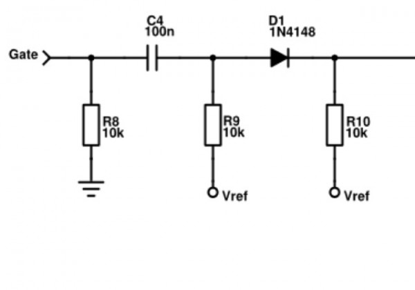
But you could try increasing the value of the 10nF cap to see if that makes a difference. Also if you plan to hardwire it you
could leave out the 1K resistors on the output of the gate-to-trigger converter. It does indeed work as a voltage divider but
the voltage should be high enough.
_________________
"My perf, it's full of holes!"
http://phobos.000space.com/
SoundCloud BandCamp MixCloud Stickney Synthyards Captain Collider Twitch YouTube |
|
|
Back to top
|
|
|
AlanP
Joined: Mar 11, 2014
Posts: 746
Location: New Zealand
Audio files: 41
|
| Posted: Tue Jul 09, 2019 3:42 pm Post subject:
|
|
|
| If the voltage from the gate-to-trigger is sagging, I'd suggest an opamp buffer of some sort on the output. |
|
|
Back to top
|
|
|
PHOBoS
Joined: Jan 14, 2010
Posts: 5947
Location: Moon Base
Audio files: 709
|
| Posted: Wed Jul 10, 2019 9:03 am Post subject:
|
|
|
| AlanP wrote: | | If the voltage from the gate-to-trigger is sagging, I'd suggest an opamp buffer of some sort on the output. |
The gate-to-trigger already uses an opamp (as a comparator) so I don't think that would do anything but for a higher current a transistor on the output
(as suggested in the circuit) would work. It shouldn't be needed though.
| e1999 wrote: | | I'm measuring with the voltmeter on the breadboard. It reads out 7.5v when the trigger hits, but as soon as I connect the trigger to the drum circuit it goes down to 3v read-out. |
Do you have a voltmeter with a capture mode or is it analog ? Because the pulse is rather short and to get a good look at the level an oscilloscope would be
preferable. I also don't really see anything in the circuit that could cause the level to be so low.
_________________
"My perf, it's full of holes!"
http://phobos.000space.com/
SoundCloud BandCamp MixCloud Stickney Synthyards Captain Collider Twitch YouTube |
|
|
Back to top
|
|
|
e1999
Joined: Apr 25, 2019
Posts: 29
Location: naples
|
| Posted: Wed Jul 10, 2019 3:27 pm Post subject:
|
|
|
Well I changed the cap in the gate to trigger converter to .1uf and it did make some difference. I also decided I'll run this at 12v whenever I decide to solder it together, so that brought the voltage of the trigger up to 5v according to the multimeter. It is now noticeably fuller although it still doesn't slap quite as hard as when I trigger it from the dr.110. Ok it's not a huge deal:) Just mostly curious. When I have time I'll try to breadboard the 110 trigger out.
As for the voltage reading- I know its def not the most faithful measurement ever. I'm just using a cheap voltcraft multimeter. But it does seem odd to me that it reads 7.5v before connecting to the drum circuit input and then as soon as I connect it, it goes down to 3v. Also, I'd have thought that a diode at the trigger output of the ken stone circuit wouldn't really do anything since there's already one on the trigger input of the twin t, but it does seem to help a little bit somehow.
Speaking of which- my understanding, please correct my if I'm mistaken, was that the diode at the output of a cv source is just there to protect the cv source in case you connect it to anything that's not playing nice. Which in fact I fried 2 4069's by connecting lfo to a cv input of a -5/+5v synth (even if the datasheet of the 4069 says it should be able to handle receiving up to -10v). But adding the diode protection also kept the range of the lfo intact when routing it into other single supply circuits I had on the same breadboard. In that instance I had a cv controlled cross fader circuit, and plugging the lfo output into the cv input without the diode and a 10k to ground changed the range from 0-8v to something like 3.5-6.5v - which regardless of how vaguely inaccurate my measuring tool is , the difference was very much audible in the resulting sound. |
|
|
Back to top
|
|
|
PHOBoS
Joined: Jan 14, 2010
Posts: 5947
Location: Moon Base
Audio files: 709
|
| Posted: Sun Jul 14, 2019 6:36 am Post subject:
|
|
|
Another thing you could try is leave the capacitor out, actually just leave everything out up to the 100K resistor to GND
connected to the opamp. I don't really see why you'd need a gate to trigger converter in the first place and this would
just boost (and shape) the signal.
A diode can work as protection but that depends on the circuit, all it does is pass current in one direction and prevent it from flowing
in the other direction. For my lunetta modules I use diodes on the outputs so I can connect multiple outputs together without
shorting them. However i'd still short it if I connect an output to GND (or negative voltage) which is why I also use resistors to limit
the current.
I don't know where you get the -10V for the 4069 from but connecting it to a CV input should normally not cause any problems.
Unlesss you connect a negative voltage to an input that can only take a positive voltage but it sounds like it's the other way around
in your case. Maybe it has something to do with the 4069 having an unbuffered output.
_________________
"My perf, it's full of holes!"
http://phobos.000space.com/
SoundCloud BandCamp MixCloud Stickney Synthyards Captain Collider Twitch YouTube |
|
|
Back to top
|
|
|
JovianPyx

Joined: Nov 20, 2007
Posts: 1988
Location: West Red Spot, Jupiter
Audio files: 224
|
| Posted: Sun Jul 14, 2019 6:55 am Post subject:
|
|
|
Gate to trigger can be needed depending on the design of the circuit being driven.
There are some circuits that are activated on rising edge of trigger and there are others that are activated on the falling edge.
If rising edge, then there is no need for a differentiating capacitor and gate can be connected directly. If falling edge, however, when activated by gate, the activation can be very late.
This is never a problem when a differentiating gate-to-trigger is used. I would suggest a schmitt trigger gate buffer at the output however. That will "square up" the differentiated output signal and give a nice clean trigger at logic levels.
_________________
FPGA, dsPIC and Fatman Synth Stuff
Time flies like a banana.
Fruit flies when you're having fun.
BTW, Do these genes make my ass look fat?
corruptio optimi pessima
|
|
|
Back to top
|
|
|
e1999
Joined: Apr 25, 2019
Posts: 29
Location: naples
|
|
|
Back to top
|
|
|
JovianPyx
Joined: Nov 20, 2007
Posts: 1988
Location: West Red Spot, Jupiter
Audio files: 224
|
| Posted: Sun Jul 14, 2019 11:15 am Post subject:
|
|
|
Because of the schmitt trigger input of the 40106, it would not make a good "linear amplifier". If you want to simply buffer, then an opamp in voltage follower mode (output connected directly to inverting input and input signal applied to non-inverting input) would be best (and no resistors needed).
With a buffer such as 40106, the circuit can drive several inputs, so the buffer would eliminate the need for a gate to trigger circuit for each. Note that a 40106 is an inverter with schmitt trigger inputs. This means that the output will be inverted. You can do one of two things to correct the inversion. Simply add a second 40106 gate, or use an opamp inverting amplifier with a gain on one. (inverting amplifier where feedback R is the same as the input R. I'd probably just use another 40106 gate unless there is a need for an opamp buffer closer to the circuit's input, then I'd use an inverting opamp circuit which creates one inversion and then a single 40106 gate will correct it.
_________________
FPGA, dsPIC and Fatman Synth Stuff
Time flies like a banana.
Fruit flies when you're having fun.
BTW, Do these genes make my ass look fat?
corruptio optimi pessima
|
|
|
Back to top
|
|
|
PHOBoS
Joined: Jan 14, 2010
Posts: 5947
Location: Moon Base
Audio files: 709
|
| Posted: Sun Jul 14, 2019 11:45 am Post subject:
|
|
|
| Quote: | | I found that I needed the gate to trigger when using a 4017 as a sequencer. I tried several different variations but wasn't able to get it to trigger reliably unless I made a gate to trigger for each of the individual steps' pulse output ie 10 steps - 10 gate to trigger converters. |
Is the problem that you don't get seperate pulses for each step ?
If that is the case then have a look at the "Little Gate" sequencer, especially the function of U1b (and U1a).
_________________
"My perf, it's full of holes!"
http://phobos.000space.com/
SoundCloud BandCamp MixCloud Stickney Synthyards Captain Collider Twitch YouTube |
|
|
Back to top
|
|
|
e1999
Joined: Apr 25, 2019
Posts: 29
Location: naples
|
| Posted: Tue Jul 16, 2019 3:18 pm Post subject:
|
|
|
thanks for the link to your schematic:)
I was able to get pulse per step, but not reliably with every eg/vca / twin t circuit that I tried.
your Little Gate Sequencer is v elegant design and works really well in that regard.
By chance have you ever used this with pots to control the dynamic volume of an eg/vca or twin-t?
this was the other limitation I experienced previously, which I've only been able to workaround by using a gate to trigger for each individual step.
this kind of dynamic triggering should work without the gate to trigger, no? Maybe its just the particular env / twin t circuits I'm using? |
|
|
Back to top
|
|
|
PHOBoS
Joined: Jan 14, 2010
Posts: 5947
Location: Moon Base
Audio files: 709
|
| Posted: Tue Jul 16, 2019 4:26 pm Post subject:
|
|
|
No, I've never used it with pots. For an eg/vca it could work if you have seperate inputs for triggering and CV.
With a twin-T you probably only have a trigger/gate input but you could indeed vary the voltage for some dynamic effects.
The problem is that the signal has to go low between steps otherwise it would just be a continuous but varying voltage and
that doesn't retrigger a twin-T. In the Little Gate Sequencer the (N)AND gate takes care of this but that only works for digital
signals (like the outputs of he 4017) not for analog voltages. So you'd need an analog AND gate. You could use a VCA for this
which might give you the best result but is probably a bit overkill. I think it should be a doable with a transistor or maybe even
just a diode and a resistor although I would only use that for a hardwired (not patchable) circuit.
With a transistor you'd wire up the 4017 like a basic baby 10 sequencer and connect the CV output to the collector of an NPN
transistor. The base of this transistor is controlled by the CLK signal (that also controls the 4017) The emitter of the transistor
will be the output (might be good to also add a resistor from this output to GND).
Another thing you can do is vary the pulse length, basically what you could do with an eg. An NE555 in monostable mode could
be used for this. Use pots on the 4017 to control the CV input of the 555 (pin 5) to set the length and have it triggered by the CLK.
You could even combine them so a varying voltage & varying pulse length and use 2 pots pers step so you can control each individualy.
_________________
"My perf, it's full of holes!"
http://phobos.000space.com/
SoundCloud BandCamp MixCloud Stickney Synthyards Captain Collider Twitch YouTube |
|
|
Back to top
|
|
|
e1999
Joined: Apr 25, 2019
Posts: 29
Location: naples
|
| Posted: Fri Jul 19, 2019 1:44 am Post subject:
|
|
|
thanks for the reply, this clarifies a lot of things
| Quote: |
Another thing you can do is vary the pulse length, basically what you could do with an eg. An NE555 in monostable mode could
be used for this. Use pots on the 4017 to control the CV input of the 555 (pin 5) to set the length and have it triggered by the CLK. |
very interesting, def going to try this out |
|
|
Back to top
|
|
|
|

 Forum index » DIY Hardware and Software » Ken Stone designs - CGS