| Author |
Message |
scowler1
Joined: Oct 22, 2019
Posts: 4
Location: USA
|
 Posted: Sat Mar 07, 2020 2:18 pm Post subject:
VCF-1 Self-Oscillating issue Posted: Sat Mar 07, 2020 2:18 pm Post subject:
VCF-1 Self-Oscillating issue
Subject description: Will it self oscillate on a +/-12V power supply? |
  |
|
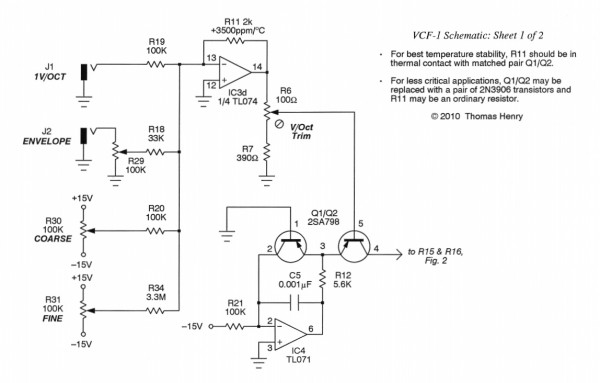
I've just bread-boarded the VCF-1 and it sounds great and seems to be working well, but it will not self-oscillate. Not a huge issue but I do feel I'm missing out!
I'm using an LM13700, a TL074 and a TL072. Transistors are a matched pair of 2N3906's and I'm using a 12V+/- power supply. Everything else just like the schematic from Scott's website.
I'd love to get this thing squealing so any suggestions would be most welcome.
Thanks to all. |
|
|
Back to top
|
|
 |
JovianPyx

Joined: Nov 20, 2007
Posts: 1988
Location: West Red Spot, Jupiter
Audio files: 224
|
| Posted: Sun Mar 08, 2020 7:09 am Post subject:
|
|
|
Hi and welcome to electro-music.com

You will get better help results if you post either a link to the schematic or the schematic itself.
As for the VCF while I don't know VCF-1, self oscillation is a function of the feedback circuit for resonance in a filter with more than one pole. That is where the problem is. I would first google to learn if VCF-1 users commonly get self oscillation without any modifications. If that is true then there is probably some build error such as wrong component value or even a bad solder joint. If it needs a mod to self-osc, you need to find it.
_________________
FPGA, dsPIC and Fatman Synth Stuff
Time flies like a banana.
Fruit flies when you're having fun.
BTW, Do these genes make my ass look fat?
corruptio optimi pessima
|
|
|
Back to top
|
|
|
scowler1
Joined: Oct 22, 2019
Posts: 4
Location: USA
|
|
|
Back to top
|
|
|
scowler1
Joined: Oct 22, 2019
Posts: 4
Location: USA
|
|
|
Back to top
|
|
|
JovianPyx
Joined: Nov 20, 2007
Posts: 1988
Location: West Red Spot, Jupiter
Audio files: 224
|
| Posted: Sun Mar 08, 2020 11:15 am Post subject:
|
|
|
State variable filter.
So the filter is designed to and should be able to go into self oscillation. I would suspect that there is something not right with the build. Check all parts values. With breadboards, one never knows. It might help to tear it all down and rebuild it.
_________________
FPGA, dsPIC and Fatman Synth Stuff
Time flies like a banana.
Fruit flies when you're having fun.
BTW, Do these genes make my ass look fat?
corruptio optimi pessima
|
|
|
Back to top
|
|
|
JovianPyx
Joined: Nov 20, 2007
Posts: 1988
Location: West Red Spot, Jupiter
Audio files: 224
|
| Posted: Sun Mar 08, 2020 11:25 am Post subject:
|
|
|
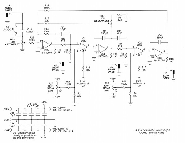
Looking at the resonance circuit, I see that one end of the resonance pot is almost grounded. It's got a 47 ohm resistor to ground. So it can almost eliminate the signal coming from that stage. Make sure it's a 47 ohm resistor and make sure there's no breadboard funkiness with it's connection. If it's more than 47 ohm, it could act like you describe. funky breadboard connection could increase the resistance. This matters more when there's a situation like that.
_________________
FPGA, dsPIC and Fatman Synth Stuff
Time flies like a banana.
Fruit flies when you're having fun.
BTW, Do these genes make my ass look fat?
corruptio optimi pessima
|
|
|
Back to top
|
|
|
scowler1
Joined: Oct 22, 2019
Posts: 4
Location: USA
|
| Posted: Sun Mar 08, 2020 9:38 pm Post subject:
|
|
|
Thanks for all your suggestions. I've tried everything, including a full rebuild, changed the chips several times, checked the values of everything and it's pretty much the same.
I think the resonance circuit is letting it down but it still sounds good so I'll probably try it on stripboard anyway.
Any more ideas are much appreciated! |
|
|
Back to top
|
|
|
|

 Forum index » DIY Hardware and Software » Thomas Henry designs