| Author |
Message |
warpeggio
Joined: Oct 14, 2020
Posts: 9
Location: St. Louis, Missouri, USA
|
 Posted: Wed Oct 14, 2020 7:02 am Post subject:
VCO-1 Stripboard Layout with 12V mods Posted: Wed Oct 14, 2020 7:02 am Post subject:
VCO-1 Stripboard Layout with 12V mods |
  |
|
Hello fellow nerds!
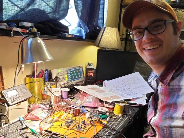
I'm Warpeggio, first time posting here. I've set out to build a synthesizer, and having completed a build of Ray Wilson's Wall Wart Power Supply, I was ready to try my hand at a VCO.
I come from the 9v world of guitar effects pedals, so i was thrilled that Thomas' design called for such simple parts that I already had in my war chest. I was a little concerned about the CA3080, but i had LM13700 at hand, and others have written positively about it as a sub / replacement. Another design goal was working off +/-12V, so my part values reflect that. I have to thank Osal for his wonderful post here on those 12v modifications.
I've come to share my stripboard layout for VCO-1. I've built it up to the point that i'm comfortable calling it "verified", although i have not the rack to test the FM or PWM functions yet. The triangle, sine, and pulse outputs are working as described.
Problems that i am currently working through:
1) With stable or no CV input, there is significant oscillator frequency instability over the course of seconds. My Rigol DS1054 won't give a clean frequency count. I *believe* this is because i have a poor power supply transformer but haven't tracked it down yet.
2)I can't test the 1v/Oct trimmer functionality because i didn't have any 100Ohm trimmers. Small-bear will be shipping some to me shortly, so until then I can't comment on how this particular build tracks.
3) I've "parked" the unused half of the LM13700, but I'd like to use it somehow. I'm currently investigating a very simple VCA, since those are always welcome.
Thanks for all the information y'all have shared on this site. Your feedback is appreciated.
Changelog:
V 2020-10-15:
* R47 was not correctly tied to the positive rail, instead misplaced on a bus with the R02 wiper. Fixed.
* C7 tied to lower ground rail to better fit capacitor pin spacing. Allows tidier jumper nearby.
* Color coded resistors involved in choosing +/-12V or +/-15V, provided table for 15V values
* Credited Osal directly in image
V 2020-11-20:
* Updated values for C13 & C14 to be displayed in the BOM
* Some minor opacity adjustments for clarity
* Fixed the extra copper strip that was displayed at the bottom of each board
| Description: |
|
| Filesize: |
533.23 KB |
| Viewed: |
424 Time(s) |
| This image has been reduced to fit the page. Click on it to enlarge. |
|
| Description: |
| Thomas Henry's VCO-1, on stripboard, modified for +/-12V |
|
| Filesize: |
538.45 KB |
| Viewed: |
1121 Time(s) |
| This image has been reduced to fit the page. Click on it to enlarge. |

|
Last edited by warpeggio on Fri Nov 27, 2020 7:58 am; edited 1 time in total |
|
|
Back to top
|
|
 |
warpeggio
Joined: Oct 14, 2020
Posts: 9
Location: St. Louis, Missouri, USA
|
| Posted: Sat Oct 17, 2020 12:35 pm Post subject:
|
|
|
Hello again! An update on the issues i was working through:
1) Instability: The scope revealed that my CV input signal wasn't as stable as i thought, and this was compounded by my poor power supply transformer responding to varying loads elsewhere in the house. Overall, the oscillator is as stable as designed.
2) Tracking over 3 octaves is excellent, although tuning can be tricky. I went back and forth between the scope and a clip-on instrument tuner. My build DOES go flat on the fourth octave - i believe it's because i used 2x 2N3906 that i didn't even try to match for current or Vbe. I assume this would be improved with a matched pair or dual IC. Personally, 3 octaves is pretty dang musical for a first VCO so i'm not sure i care to make any changes.
3) I've drawn up a version that implements a simple VCA on IC1B, but i haven't built it yet. It's based on a design that Kristian Blåsol shared on his Youtube. This would be a "no-frills" design, to say the least. |
|
|
Back to top
|
|
|
mikeb
Joined: Nov 20, 2006
Posts: 59
Location: The Automotive Capital of Canada
|
| Posted: Fri Nov 06, 2020 5:54 pm Post subject:
|
|
|
[quote="warpeggio"
3) I've drawn up a version that implements a simple VCA on IC1B, but i haven't built it yet. It's based on a design that Kristian Blåsol shared on his Youtube. This would be a "no-frills" design, to say the least.[/quote]
If you do use the other half of the 13700 for something, I suggest closely watching the frequency of your VCO as you operate the shared VCA. From my experience using it in a very similar way about 10 years ago, my oscillator fluctuated around 5-10 cents. |
|
|
Back to top
|
|
|
Gingoism
Joined: Feb 01, 2017
Posts: 23
Location: Singapore
|
| Posted: Mon Nov 16, 2020 6:48 pm Post subject:
|
|
|
agreed, in an earlier design i used the 2nd half as an FM VCA and it messed with the osc core majorly...now the vco sits on my desk as a test osc.
However in a more recent design i used the 2nd half as a sine shaper instead...which is a better use of the spare ota imo. |
|
|
Back to top
|
|
|
warpeggio
Joined: Oct 14, 2020
Posts: 9
Location: St. Louis, Missouri, USA
|
| Posted: Fri Nov 27, 2020 8:15 am Post subject:
|
|
|
| mikeb wrote: | | warpeggio wrote: |
3) I've drawn up a version that implements a simple VCA on IC1B, but i haven't built it yet. It's based on a design that Kristian Blåsol shared on his Youtube. This would be a "no-frills" design, to say the least. |
If you do use the other half of the 13700 for something, I suggest closely watching the frequency of your VCO as you operate the shared VCA. From my experience using it in a very similar way about 10 years ago, my oscillator fluctuated around 5-10 cents. |
| Gingoism wrote: | agreed, in an earlier design i used the 2nd half as an FM VCA and it messed with the osc core majorly...now the vco sits on my desk as a test osc.
However in a more recent design i used the 2nd half as a sine shaper instead...which is a better use of the spare ota imo. |
Thanks for the notes, Gingoism and mikeb! I'll leave the second half "parked" for now, and simply note that there is half of an LM13700 available for modding as the user sees fit. 
I did a complete second build of this module. I matched transistors using Ian Fritz's method, a 2k tempco bonded to the top (LT732K0JTG from Small-Bear), and a polystyrene cap for C3. I let it warm up for 20 minutes, and then with my skill and a clip-on tuner, i was able to get 4 solid octaves out of it. I am not confident that i did the procedure exactly correct, and i have doubts about my 1v/Oct controller, but i think there still may be some room for improvement on the stripboard layout.
That said, I think that the target audience should be comfortable with these tradeoffs, if not challenged to one-up my results. A VERY playable VCO built with (mostly) common components and without etching or waiting for a custom PCB. If you choose to build this with NO care on matching transistors, tempco, or polystyrene, i just recommend that you let the module get GOOOD and warm before attempting to use / tune it. Unmatched, the pitch will jump cents and whole tones as the temperature equalizes between the two transistors, but once it's warmed up, it's accurate enough!
I hooked this module up to a MIDI controller and was very pleased with musicality of the result.
| Description: |
| Open the image to see it rotate and show the backside(s) |
|
| Filesize: |
1.73 MB |
| Viewed: |
398 Time(s) |
| This image has been reduced to fit the page. Click on it to enlarge. |
|
|
|
|
Back to top
|
|
|
R_Gol
Joined: Oct 17, 2019
Posts: 34
Location: World
|
| Posted: Thu Dec 31, 2020 8:00 am Post subject:
|
|
|
Thanks for sharing this!
My I ask you regarding two things:
All pots are in back view? lugs are from top to button is 3 2 1 ?
Can I omit the c12 (0.22uf) if I would like to make that input dc coupled? (same as the exp fm input?) |
|
|
Back to top
|
|
|
warpeggio
Joined: Oct 14, 2020
Posts: 9
Location: St. Louis, Missouri, USA
|
| Posted: Fri Jan 01, 2021 11:51 am Post subject:
|
|
|
| R_Gol wrote: | Thanks for sharing this!
My I ask you regarding two things:
All pots are in back view? lugs are from top to button is 3 2 1 ?
Can I omit the c12 (0.22uf) if I would like to make that input dc coupled? (same as the exp fm input?) |
1. Yep, that's a back view of the pot. Let me know if you find any errors regarding clockwise / counterclockwise functioning.
2. I don't know for sure. Looking at "Richard Brewster's version of CGS/ASM VCO" in another thread, there's a switch that allows this, so MAYBE? I can't really speak to it, other than to say give it a try and see what happens! |
|
|
Back to top
|
|
|
JimRead
Joined: Nov 07, 2021
Posts: 9
Location: uk
|
| Posted: Sun Feb 06, 2022 10:24 am Post subject:
|
|
|
Hello,
I really like this build fair play to you for doing it, I use 12v so it would be a boon to me.
I wondered if I made two of them is there any way to synchronise them?
Cheers - Jim |
|
|
Back to top
|
|
|
|

 Forum index » DIY Hardware and Software » Thomas Henry designs
