Joined: Jan 14, 2010 Posts: 5950 Location: Moon Base
Audio files: 709
Posted: Sun Nov 14, 2021 7:32 am Post subject:
pixels & scanlines Subject description: video synthesis, circuits, demos and links
About a year ago I went down the rabbit hole of video synthesis and other means of creating video art.
I've been wanting to work with video for a looong time, way before I started making music, but couldn't afford the gear
and didn't have a computer that was capable of processing or recording any of it (also too expensive).
Fast forward to April 2020 when I began streaming on twitch and since it's a visual medium and I now had a PC that
was somewhat capable of working with video I started trying some things. In this thread I will be positing what I have
been doing and discovered since then.
Visual Jockey VJ software
I believe one of the first things I messed around with was Visual Jockey that I had seen being used by Laura woodswalker.
It is rather outdated software but capable of doing some very nice things. The quailty is a bit low though or too CPU hungry,
at least when using it realtime, but it can render at a higher quality.
here are 2 examples:
This first one only uses some blending, zooming and color changing effects.
This second one makes heavy use of the kaleidoscope effect and the audio responsive features. (music by Six Umbrellas)
For both videos I only used still images as a source.
Joined: Jan 14, 2010 Posts: 5950 Location: Moon Base
Audio files: 709
Posted: Sun Nov 14, 2021 8:25 am Post subject:
OBS Studio effects
Using OBS Studio for video processing
After that I began messing around with OBS studio to see what I could do with it. Allthough it is not really designed
as VJ software it can mix and blend multiple sources, adjust colors, change the shape, move things around an also
create video feedback. I haven't even looked into shaders yet which opens up a whole new dimension of videoprocessing.
For video feedback you can make use of the OBS virtual camera but it is very buggy, at least for me, to the point that
I ended up not being able to use OBS at all anymore*, so be warned!. Another way is using display capture and that works
very well for me when using a second monitor.
Here's an example that uses the scrolling feature to create somewhat of a kaleidoscopic effect combined with video feedback.
I might have also used Visual Jockey for this one or maybe it has another source video mixed in.
For this one I just mixed multiple sources, most are actually animated gifs.
Around august 2020 I figured out how to install droidcam so was able to use an old phone as a webcam. The quality is low for the free version
but at least it was something. I happened to have a set of small lenses that can be clipped on a phone and one of them is a fisheye lens so that came
in very useful. Finally I could offer a view of the Moon Base in realtime. https://youtu.be/hZ8Y_dDj3rw (not much new going on visually besides the cam)
Joined: Jan 14, 2010 Posts: 5950 Location: Moon Base
Audio files: 709
Posted: Sun Nov 14, 2021 10:29 am Post subject:
twitch streamer links
Video Art on Twitch
In the meantime I had been invited to join the AVglitchclub discord channel which is a small community of twitch streamers
that are interested in different forms of visual art. Mostly involving analog video processing. So here's a list of twitch streamers
that I think are worth checking out if you like that kind of stuff:
AVglitchclub members: Tremendm Labs: 'Analog Acid Glitch' They have a weekly show on mondays (sadly too late for me) in which they process classic VHS movies
and a show on thursdays where they play cassettes and create more abstract visuals. Some of the glitched movies are available on VHS at their bandcamp page.
Occasionally they create music themselves and you can find some great music by Dr. Mysterium here and some older videos on their youtube channel.
VHS Acid Glitch movie clip: https://www.twitch.tv/tremendm_labs/clip/DistinctOilyLocustPeteZaroll-WclhXBghq-Qh4sT7
The Forgotten Astronaut: 'Cosmic Adventures' Old school projections, liquids, video feedback, practical effects and analog processing with a story line.
Has a massive setup which he joyfully explains.
Gridworks; Weekly liquid light shows and occasional movie nites.
P_Chops: Free brainwipes to obtain oppulent luxury. Can't say too much about it you just have to stare at the purple chickens and experience it for yourself.
Some of my video experiments have made it into the neural programming.
theb_roll: hasn't been very active lately but combines modular synthesis with live video sampling. There is some great content on youtube
Joined: Jan 14, 2010 Posts: 5950 Location: Moon Base
Audio files: 709
Posted: Sun Nov 14, 2021 12:36 pm Post subject:
Andrei Jay & Video Waaaves
Andrei Jay & Video Waaaves
I think it was also through the AVglitchclub that I became familiar with software developed by the genius that is Andrei Jay,
most notably Video Waaaves. With Video Waaaves you can create video effects which are reminiscent of the classic
camera-pointed-at-a-screen feedback but it can go way beyond that and with the advantage of digital processing including
all kinds of modulation, transformation, long delays, color shifting, and at a high resolution. (also has midi control)
There are standalone pi-based hardware versions available aswell which include some audio control but they are quite expensive .
The software is open source and available for linux, windows and OSX but does require Visual Studio for windows (don't know about linux/OSX)
So I gave it a try to see what I could do with it. My PC wasn't too happy with it especially since I was also streaming so I had to keep the resolution
pretty low which suffered even more from the encoding in OBS. But here are some results (note that I went in blind just figuring it out on the fly):
This one used V2.0 which worked better for me or at least my PC than V2.5
This one is from a session in which I used V2.5 with a notable drop in quality (next one is from the same session but might still have used V2.0)
Joined: Jan 14, 2010 Posts: 5950 Location: Moon Base
Audio files: 709
Posted: Sun Nov 14, 2021 2:32 pm Post subject:
VGA experiments
VGA Experiments
So far I'd only been messing around with software but I don't like to rely on a PC and the one I have is a bit outdated to begin with.
I prefer hardware and of course to build things myself and incorporate it with my other gear. The first thing that got me started on that
was Ben Eater's world's worst video card. If you are not familiar with Ben Eater he has an excellent series on youtube in which he builds
and explains an 8-bit breadboard computer from scratch.
This VGA video card creates the necessary sync and RGB signals with discrete logic. I did things a little bit differently and replaced
a couple of the gates with diodes but it actually worked I think I also used a different resolution because I had to use a different
crystal and for the RGB signals I used resistors to create 3 bit inputs + a CD4053 to create proper blanking during the sync intervals.
(I can't seem to find a complete schematic right now but I'll add it if I do)*
What was immediately fun to do was creating RGB signals by using a combination of logic chips, it's like an instant video lunetta.
For this I made use of the outputs from the dividers that create the sync signals. Using these directly to control the RGB signals results in
horizontal and/or vertical bars in different sizes. With an OR gate you get both (cross), with an AND gate you get squares, and with
an XOR gate you get a checkerboard pattern. Combine 'em and you get combinations.
One of the first things I just had to try was the sierpinsky pattern generator and that worked perfect (see attachments).
After that I tried to create some sort of animation or at least the illusion of movement which resulted in this:
I did end up with a test circuit that I could control with external signals and at one point used an arduino for this but it was all pretty basic
and to get more interesting shapes and effects would require quite a bit of logic. You can feed different signals into the RGB inputs directly
but if they aren't synced in any way it gets messy and you need high frequencies for anything substantial.
*I added a schematic. It's not entirely complete as I did use a regular crystal which required some more components than a crystal
oscillator and I am not sure if it does indeed have a resolution of 600 x 400, but it should give you an idea of how it works.
20201206 - VGA testvoard V1 - 01.jpg
Description:
Filesize:
375.32 KB
Viewed:
353 Time(s)
This image has been reduced to fit the page. Click on it to enlarge.
20201206 - VGA testvoard V1 - 02.jpg
Description:
Filesize:
240.33 KB
Viewed:
355 Time(s)
This image has been reduced to fit the page. Click on it to enlarge.
20201206 - VGA testvoard V1 - 03.jpg
Description:
Filesize:
251.75 KB
Viewed:
346 Time(s)
This image has been reduced to fit the page. Click on it to enlarge.
VGA TEST BOARD [400x600].gif
Description:
Filesize:
142.72 KB
Viewed:
359 Time(s)
This image has been reduced to fit the page. Click on it to enlarge.
Joined: Jan 14, 2010 Posts: 5950 Location: Moon Base
Audio files: 709
Posted: Sun Nov 14, 2021 3:00 pm Post subject:
CHA/V and more VGA experiments
Looking around on the web to learn more about VGA signals I came across the CHA/V
The CHA/V is a very simple device that uses a cheap VGA test pattern generator (you can get them for < 5,-)
to create the sync signals and then hacks into the RGB signals to create glitchy effects. To quote the website:
Quote:
Who is this for?
“I want my modular synth to make purdy-pitchers while I play it”
“I like making DIY audio circuits, like the Atari Punk Console. Is there something like that for video?”
“I’m interested in DIY video devices or circuit-bending.”
“I’ve heard of a soldering iron, and I am willing to do some online research about reading a schematic, learning to solder, and I’m not afraid to maybe break a few of these, burn my fingers, and/or receive a minor electrical shock.”
The CHA/V is not:
the “correct” way to synthesize video
made from quality parts
capable of precision
well-behaved
I could already generate sync signals but this is a much easier (and smaller) way to create them and the VGA test generator can switch between
different resolutions. However it does not have all the outputs from the dividers available (multiples of the sync signals) which I made use of to
create anything stable on the screen but it does offer something else that is very useful; synced oscillators.
These oscillators are just your standard 40106 schmitt trigger inverter oscillators with one small difference, the timing capacitor is not
connected to GND but directly to one of the sync signals. I am surprised I haven't come across this method before in lunetta land as it
works remarkably well and is of course also useful for audio synthesis. Add a switch and you can un-sync them to get lines that scroll
across the screen.
Joined: Jan 14, 2010 Posts: 5950 Location: Moon Base
Audio files: 709
Posted: Sun Nov 14, 2021 6:10 pm Post subject:
modified v-guard VA203
Modified v-guard VA203
VGA is pretty easy to work with and definitely useful but I also want to use different analog video sources that use composite video.
One thing I had found out by now is that the analog video processing I've seen other people do is mostly done with custom modified
vintage gear and there isn't a lot out there when it comes to schematics. You can find some of that gear here and here.
Many years ago I got myself a simple videoswitcher with the idea that it might come in useful one day so I dug it up to see if I could do anything
with that. It is a v-guard va203 and it doesn't do a lot besides selecting 1 of 4 video/audio inputs and it has an audio mixer to mix in a mic and/or
external audio source. It also has 2 knobs to adjust the video signal a bit. I decided to open it up and mess around with the circuitry, shorting things
together to see if I could get anything more interesting out of it. Nothing would be lost in case I'd break it as I wasn't using it for anything and got it
very cheap at the time.
I didn't get the most interesting effects out of it but was able to produce some glitches, and I added some oscillators and external CV inputs.
For the CV inputs I did some tests using a color organ that I originally created as part of the visualist* (I can now get back to that one aswell)
to create audio controlled glitches.
here's one of the results which also made use of OBS Studio for videoprocessing, feedback and additional media.
capturing was done with a cheapo easyCAP USB device so not the best quality, but it didn't matter much for this.
here's another example in which I overloaded OBS a bit resulting in an even worse quality. I later cleaned up some scenes in OBS after it
crashed because of the virtual cam which caused a significant drop in CPU usage (roughly from 70% to 10%) which has made it possible to use
some higher quality settings. There was also a noticable delay caused by the capturing which I later adjusted in OBS by delaying the audio.
the video is unlisted because the music was created by Epicyclus.
Joined: Jan 14, 2010 Posts: 5950 Location: Moon Base
Audio files: 709
Posted: Sun Nov 14, 2021 7:20 pm Post subject:
video feedback with cheap video converters Subject description: part 1
Video feedback with video converters - part 1
While trying to find more useful video circuits and looking at what other people had created I stumbled upon
some very nice looking devices by George Gleixner. Most of these devices are based on the same concept of
creating an internal feedback loop and after digging around a bit deeper I found out that it is done using two
video converters. One converts composite to VGA, the other converts VGA to composite. Some basic info about
how to connect them can be found here
There is also more information including schematics on the Gleix website but as I found out later it uses an older
model converter which had a RAM chip and that made it possible to add a patchbay. There is another converter that's
still available to which a patchbay can be added but it's a slightly more expensive and it requires soldering a lot of
small wires to an SMD chip. If you want to give it a go you can find an instructional video here.
I ordered the converters and tried it out. It takes a while to figure out useful settings on both converters,
which use a menu and an onscreen display, but after that it can create some very nice colorful effects.
here's one of the first experiments that also used the modified VA203 in the feedback loop and I used OBS Studio
to add some additional feedback, mirroring and filter out all the green color to create some empty space.
_________________ "My perf, it's full of holes!" http://phobos.000space.com/ SoundCloudBandCampMixCloudStickney SynthyardsCaptain ColliderTwitchYouTube Last edited by PHOBoS on Mon Nov 15, 2021 9:35 am; edited 2 times in total
Joined: Jan 14, 2010 Posts: 5950 Location: Moon Base
Audio files: 709
Posted: Sun Nov 14, 2021 8:13 pm Post subject:
video feedback with cheap video converters Subject description: part 2
Video feedback with video converters - part 2
Since I already knew a thing or two about VGA signals it made sense to do some processing between the 2 converters.
The Gleix devices have some simple LFO's and level controls for RGB signals but I thought I could do a bit more than that.
Instead of just attenuating RGB levels why not mix them with a matrix mixer. This should make it possible to create different
color palettes and even do some hue cycling. Some synced oscillators that are used in the CHA/V could also be useful.
Initially my plan was to create a standalone device similar to this one and because the converters use a 5V DC supply
I wanted to use that as the supply voltage for anything else I added aswell. Because of this low single supply voltage,
high frequencies and low signal voltages I tried doing it with transistors instead of opamps (the TLC274 would probably
have worked pretty well for it but I didn't know that yet). I experimented with some diode mixing using transistors as
buffers and actually got some pretty useful results. I posted a simplified version of the circuit I ended up using here.
Here's a test that only used 1 channel of what would be a 3x3 matrix mixer (didn't breadboard the rest before building it on perf).
I also shifted the colors by hardwiring red>green, green>blue, blue>red which causes color cycling and some heavy strobing!.
OBS was used for further processing including a scrolling motion.
here's another test with the same setup
and another test which I believe also used an oscillator or two but I ended up playing mostly with my synths for this one.
note: the B&W pattern in he background is just another animated GIF.
_________________ "My perf, it's full of holes!" http://phobos.000space.com/ SoundCloudBandCampMixCloudStickney SynthyardsCaptain ColliderTwitchYouTube Last edited by PHOBoS on Mon Nov 15, 2021 9:35 am; edited 2 times in total
Joined: Jan 14, 2010 Posts: 5950 Location: Moon Base
Audio files: 709
Posted: Sun Nov 14, 2021 9:46 pm Post subject:
analog video mixing
Mixing analog video signals
Besides processing and creating videosignals I also want to be able to mix different sources together. However this is not
something that is feasible with an analog DIY circuit. Audio signals are just simple AC voltages that can even be mixed together
using resistors. Mixing video signals on the other hand and especially composite video is a whole different ball game, and the
main problem is sync.
An analog video signal is made up of scanlines (not pixels like VGA) and the sync signal tells the receiver when a line starts (HSYNC)
and when a frame ends (VSYNC). Then there is also interlacing which means the signal alternates between even and odd scanlines
every field (half frame) and PAL makes it even more complex by also rotating the color burst signal, not to mention that the signal
itself isn't a symmetrical AC signal. But lets stick to sync for now.
If you try to mix 2 signals together that aren't in sync, and apart from some professional cameras they aren't, you'll get some
scrolling pictures at best. But most likely you'll end up with a glitchy mess as the receiver has no idea what the hell is going on.
CRT's might still create something watchable and are your best friend when it comes to glitchy video sources but anything digital
will most likely give up resulting in some sort of 'no signal' message.
This doesn't make it useless though and one well know device is the 'dirty mixer' by Karl Klomp which is nothing more than a single
pot and maybe some switches on the more "advanced" versions. There is also the 'schele mixer' by Gijs Gieskens which creates a
slightly better sync signal with the help of an LM1881 chip (very useful chip for DIY video).
My first video mixer - Panasonic WJ-AVE55
The proper way to mix analog video signals is with an actual video mixer that usually includes a timebase corrector (TBC) that can also
help (to a degree) with glitchy video sources. There aren't many new models produced for obvious reasons but you can still find some
vintage ones on the 2nd hand market. So that's where I went to look.
I had spotted a Roland Edirol V-4 but that was gone very quick before I even know what it could actually do. Once I knew more about
its features I really wanted one especially since it can mirror video (so I wouldn't need OBS for that anymore). Since I had no idea if
I would come across another one that would be affordable anytime soon (spoiler: I did) I decided to look for something else and then
maybe get a V-4 later on. What I ended up with is a Panasonic WJ-AVE55.
It's actually a pretty nice mixer with some different wipe options and a couple of simple effects. Another feature that I discovered
once I got it is that it has an RS232 serial connection which makes it possible to control every feature remotely. I already had a
MAX232 chip for RS232 communication and an arduino can send out some serial data so I wondered if I could make that work.
I huge help was this page which has an excel sheet with all the parameter values.
Also this project which helped me getting started with the code.
here are some lines of code that do most of the work
// sending parameter with no additional values
// for example VBC:147 (sets the background color to black)
strcpy(cmd, "VBC:147"); sendserial();
// sending parameter with additional values
// for example VMM:179xx to set the fader position
strcpy(cmd, "VMM:17900"); sendserial(); // sets mix to 100% channel A
strcpy(cmd, "VMM:1797F"); sendserial(); // sets mix to 50%
strcpy(cmd, "VMM:179FF"); sendserial(); // sets mix to 100% channel B
// sending parameter with additional values using variables
// for example VPS:218xxxx to set the wipe shape position
byte posX=128; // X position centered
byte posY=128; // Y position centered
sprintf(cmd, "VPS:218%02X%02X",posX,posY); sendserial();
A video mixer is also nice for video feedback, just connect the output back to one of its inputs and you're done. Well, you can mess
around with different wipes or use keying (chroma/luma) for even better effects and of course put something else in the feedback
path to process the signal.
By using the arduino to control the position, background color and size of the wipe and placing the converters in the feedback path for
color cycling I created a simple worm. The starry background was added in OBS Studio.
Panasonic WJ-AVE55 - 01.jpg
Description:
my first video mixer
Filesize:
200.83 KB
Viewed:
337 Time(s)
This image has been reduced to fit the page. Click on it to enlarge.
Joined: Jan 14, 2010 Posts: 5950 Location: Moon Base
Audio files: 709
Posted: Mon Nov 15, 2021 11:17 am Post subject:
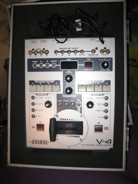
My second video mixer - Roland EDIROL V-4
As mentioned previously I wanted an EDIROL V-4 so I kept an eye out for it and within a month of getting my first mixer
I spotted one for sale for a very affordable price, it even included a flightcase. It was only just put up and I was expecting
bidding to drive the price up beyond my budget but I decided to take a shot and send the seller a message. A couple days
later I had it in my posession .
The V-4 is really geared towards VJing unlike the WJ-AVE55 which is made for video editing. It has quite a lot of wipes and
swipes and effects so I grabbed the manual and slowly made my way through it while testing everything, I streamed it live
on twitch and here are 2 excerpts. (I really like the second one.)
It also has a midi input to control some things which I could also do with an arduino but it is rather limited. The V-4 has
2 channels and you can select 1 of 4 sources for each channel. Each channel also has 4 effect buttons that you can assign
an effect to. You can also assign 3 different wipe/mix/keying transitions that can be selected with buttons. Then there are
preset banks and for each bank you can create different combinations of assigned effects and transitions.
With midi you can basically just virtually press the buttons so you can select different sources, turn the effects on/off (with
some extra settings for some effects) and select one of the 3 assigned transitions. You can also control the fader position
and the transform buttons which override the fader so you get 100% channel A or B. What you can't do with midi is choose
from any of the effects and transitions or select a different preset bank so you still have to do that manually. Which is a real
shame because it would make it a lot more useful.
Roland EDIROL V-4.jpg
Description:
my second video mixer
Filesize:
234.83 KB
Viewed:
341 Time(s)
This image has been reduced to fit the page. Click on it to enlarge.
Joined: Jan 14, 2010 Posts: 5950 Location: Moon Base
Audio files: 709
Posted: Mon Nov 15, 2021 2:01 pm Post subject:
More about video feedback
I've mentioned video feedback a couple of times and it might be good to talk a little bit more about it.
The classic feedback setup is created by connecting the output of a camera to the input of a monitor or projector
and then pointing the camera at the screen. This will create an infinite loop and just like with audio feedback
certain artifacts will get amplified or attenuated. By changing the position and angle of the camera and adjusting
settings on the camera and/or screen you can create a variety of nice flowing shapes and colors.
Of course you can also process the video signal between the camera and screen. For example if you invert it you
will usually get a black and white pattern and mirroring can also create some really nice effects. Both examples
can be seen in this video:
I also did some experiments myself with the cheapest camera I could find (2,- parking cam) and it did give some
interesting results. But the camera has a very wide angle creating a fisheye effect and it has auto-white balance
and auto-gain and well there are no settings on it. Also the quailty isn't very high which is to be expected for that
price.
What's nice about this setup is that you are actually using light, converting photons to electrons and back to photons
and you can mess around with photons. Of course changing the camera position already does that but you can also
place a (moving) object inbetween the camera and screen. You can also use more than 1 camera and if you add
more screens aswell and some glass plates you can end up with something fractalicious like this:
Another way of creating feedback is purely electronic and this is where video mixers are very useful. If you would
just take some sort of analog video processing device and connect the output back to its input it might do something
but it won't create a video signal. A video mixer on the other hand is capable of generating a video signal by itself.
Also because it has to do some complicated processing to get 2 signals in sync there is a delay and delays create a
flowing motion. Though it is not very long and can result in fast strobing. Video mixers also come with different effects
to alter the signal and luma/chroma keying can be very useful to filter parts out.
Of course a mixer can blend 2 signals together so you can insert another video signal into the feedback loop which by
itself can be another feedback loop. For example the EDIROL V-4 has 2 composite and 1 s-video output which both
create a somewhat different feedback effect. Mixing these together in different ratios with different effects applied to
both creates endles possibilities.
Using 2 video converters to create video feedback is somewhat similar to using a video mixer as they can process and
generate a video signal by themselves.
You can also use software, for example OBS Studio can do it, Resolume or some other VJ software might be able to do
it or something more dedicated like Video Waaaves.
Joined: Jan 14, 2010 Posts: 5950 Location: Moon Base
Audio files: 709
Posted: Mon Nov 15, 2021 7:50 pm Post subject:
here's my latest attempt at video feedback after adjusting the camera settings (it's also a slightly better camera)
resulting in some multispiral goodness.
Thank you for writing all this up, PHOBoS! It's fascinating to read about your explorations in videoland. I never got very far in my own, and don't seem to have the time these days.
Shortly after beginning to do "experimental" music, but before I started building electronic things, I was interested in video stuff. I wanted to run video signals through my effects pedals, but of course it didn't work. (Although much later I did manage to run video through a ring modulator sortof, but it wasn't that interesting, IIRC).
Back in 2014, Top Top had posted some promising stuff using CMOS and the LM1881, but never ended up sharing more details of the circuits (these days he's doing some pretty amazing and beautiful things that usually don't involve electronics). I couldn't figure out how to get anything out of that chip.
Great journey! _________________ Jan
also .. could someone please turn down the thermostat a bit.
9 3 4 .. erm .. not 13 then? .. hmm, ah eight! .. yeah yeah as in 8647 .. 47 is an 88 .. pwew .. numbles!
Joined: Jan 14, 2010 Posts: 5950 Location: Moon Base
Audio files: 709
Posted: Sun Nov 21, 2021 7:10 am Post subject:
Thanks for reading guys, there's more to come but I needed a break,..
I've actually wanted to start this thread a while back but I got a bit carried away testing and bulding circuits.
So now I am trying to write it down in somewhat of a chronological order going by the videos I've recorded.
RingMad wrote:
Back in 2014, Top Top had posted some promising stuff using CMOS and the LM1881, but never ended up sharing more details of the circuits (these days he's doing some pretty amazing and beautiful things that usually don't involve electronics). I couldn't figure out how to get anything out of that chip.
I will probably talk a bit more about that chip at some point. Basically you can use it to get the sync of a video signal and add it back later to get
something that still resembles a composite video signal. But you have to make sure there is no other signal during the sync. As mentioned in the
thread you linked to a 4053 (or any other mux/switch) can be used for that. But composite video is rather tricky to work with.
While looking for circuits I also came across your videffektor which I had to give a try of course. For me it only ended in a fried 4040,
which didn't surprise me, but a 4040 is fun to play with as long as you don't mess up the sync. Of course messing with the sync is what can
cause some nice glitchy effects but the outcome depends a lot on what you connect the signal to. (CRT for best results)
I am currently working on a posterizer effect which was originally published in elektor magazine and I've added some extra mods. Along those
are 2 4040s, one triggered by the CSYNC for horizontal bars and one being triggered by a synced oscillator (synced to CSYNC) to create
vertical bars resulting in this: note that I also used the colorizer on the V-4 which works really nice together with the posterizer.
Joined: Jan 14, 2010 Posts: 5950 Location: Moon Base
Audio files: 709
Posted: Sun Nov 21, 2021 7:42 am Post subject:
Two mixers is more fun than one
So now I had two video mixers and although my initial idea was to mix several video sources I find myself working
with feedback most of the time. That's also partially because I still need to connect my mediaplayer which will make
it possible to use anything else other than DVD's. But back to feedback,..
With a single mixer you can create a single feedback path (or two if you want), with two mixers you can do that for
each mixer individually but you can also create a larger loop involving both mixers. What's interesting is that both mixers
create different effects, which makes sense of course since they use different circuitry. The Edirol V-4 creates the nicest
effects when using the s-video output which results in some digital looking diagonally moving feedback. The WJ-AVE55
on the other hand has the nicest effect when using the composite output and it creates a more analog looking flowing
feedback effect.
Here are some examples involving both mixers which I believe did not use any other input signal (video ZIM)
Joined: Jan 14, 2010 Posts: 5950 Location: Moon Base
Audio files: 709
Posted: Sun Nov 21, 2021 10:20 am Post subject:
DIY video synth
As I mentioned there isn't that much available online when it comes to DIY video circuits or at least I didn't find much.
However at some point I came across a link to this google drive which has a large collection of circuits (hey look it has James' videffektor).
I may have found it on https://scanlines.xyz/ (highly recommended) or maybe it was a thread on MuffMod Wiggler.
It has a large PDF with the orginal Sandin Image Processor circuits.
Also in there is the NES Zapper VSynth Theremin by Russell Kramer that I had come across before years ago on 4chan of all places.
Russel Kramer has written some extensive descriptions of his amazing circuits here. And I'd love to get my hands on a mainbow
There are circuits by Gijs Gieskes, another amazing guy who has created some rather unusual circuits and his PCBs are a work of art in itself.
LZX Industries which is probably the biggest name at the moment when it comes to modular video synthesis. I will likely copy a lot from them in the future.
Elektor Magazine circuits including the posterizer I mentioned in the previous post.
and a lot more,..
The Archer video enhancer (has its own thread here on EM) Is one of the first ones I wanted to try and looking a bit more into it
I found the Syntonie version which has a lot of mods for glitchy effects. Actually there are 2 versions, the AVE MOD and the CBV001.
The AVE MOD is a standalone device that has an audio input, the CBV001 is a eurorack module that instead has a CV input. There are
also some variations in component values. Both inputs control different parameters so I thought "why not combine them to
have audio and CV control" and that's what I did.
When I was experimenting with the video converters I realized that it was possible to add a lot of modulation options and although my
initial idea was to make it into a standalone device it made more sense now to do it modular and add things later. I was still waiting
for some parts for the converters so the modified archer enhancer was the first module I build (didn't even have a case yet).
After I finished building it I played around with it for a bit which resulted in Blubber Dubber:
I am actually considering putting it in a standalone case and seperate video processing of composite video from video
synthesis using RGB and sync signals. It's not really convenient to use with my current setup and I do have some shorter
pieces of rackmount rails I could use so I don't have to discard the panel. Having the video connectors on the bottom is also
a bit annoying in use.
Syntonie AVE MOD V2.3 and CBV001 (PHOBoS MOD).gif
Description:
Filesize:
120.97 KB
Viewed:
320 Time(s)
This image has been reduced to fit the page. Click on it to enlarge.
Joined: Jan 14, 2010 Posts: 5950 Location: Moon Base
Audio files: 709
Posted: Sun Nov 21, 2021 12:47 pm Post subject:
Practical Effects
I don't know if it is an official term but when I say practical effects I refer to visual effects that don't use a video signal but can be combined with
video and aren't directly electronic but use objects, light, liquids and other materials. This is the more old school approach to video art most
famously used for psychedelic light shows in the 60s. Some examples can be seen in this video:
The Liquid Light Labs youtube channel also has a lot of other great videos about liquid light shows including tutorials and this one
about the history & evolution.
I have messed around a little bit with liquid slides a couple years ago but there where 2 problems I kept running into. The first problem was leakage.
Liquid slides use two glass slides with a combination of liquids inbetween which react to the heat of the lamp. The slides were 'glued' together with
silicone caulking and my main mistake was not waiting long enough for it to dry. I did a test later where I left it to dry for a couple of days before
injecting liquids and that did work better. Pressure is also a problem here because certain liquids will turn into a gas when heated which creates some
nice bubbling. It won't explode as at the very least there is a small injection hole it can escape through but can get quite messy. It is also possible that
some 'liquids' reacted with the silicone as I mixed all kinds of things including alcohol, glues, oils, liquid soaps, dyes, glycerin, and some solvents.
The other problem was the heat itself. Normally a slide projector has a thick piece of glass that acts as a heat shield to protect the slides from
melting. For liquid slide projections this has to be removed because the heat is what makes it work, similar to a lava lamp. However as it turns
out the plastic part that holds the front lens isn't heat resistant like the rest of the projector and started melting a bit. It is of course possible
to use liquid slides but you'd need one of the old school full metal slide projectors.
I also made an attachment with 2 color wheels and a warp wheel, though I did not know it was a named that and actually used in light shows.
This warp disc was made from a clear disc that you'd sometimes get with a CD spindle. I crumpled up some aluminum foil to create somewhat
of a mold, placed the disc on top and put it into the oven untill the plastic became soft and started sagging and that worked surprisingly well.
Hmm, I guess I could try to use it with a camera aswell to see what that does.
For use with video I got myself a small solar powered turntable/lazy susan. I was hoping that I could add speed- and maybe direction control
to it but it doesn't use a conventional motor so I doubt that will work. I did add a rechargable battery to it and a switch so that when there is
enough light it can use the solar panel to charge the battery and rotate (it uses very little current) and if there isn't enough light I can simply
switch to battery power.
Initially I used it to rotate objects. Here's an example that used a cardboard cylinder with a pattern taped on to it:
I also got some nice effects with one of those metal wire sponges since the rotation makes it reflect light in different directions.
My next idea was to add arduino controlled RGB LEDs which resulted in this.
Another way of using it is by printing something out on paper and placing it on top of it. Here's an example of that recorded last night.
I am also thinking of getting one of those small dichroic glass cubes to experiment with.
color and warp wheels - 01.jpg
Description:
dusty wheels
Filesize:
251.31 KB
Viewed:
266 Time(s)
This image has been reduced to fit the page. Click on it to enlarge.
color and warp wheels - 02.jpg
Description:
Filesize:
227.65 KB
Viewed:
248 Time(s)
This image has been reduced to fit the page. Click on it to enlarge.
PFX20210605A setup.jpg
Description:
Filesize:
315.11 KB
Viewed:
259 Time(s)
This image has been reduced to fit the page. Click on it to enlarge.
Joined: Jan 14, 2010 Posts: 5950 Location: Moon Base
Audio files: 709
Posted: Sun Nov 21, 2021 4:16 pm Post subject:
Arduino TVout
I remembered seeing something about generating composite video signals with an arduino so I looked it up and yes, that is a thing.
It is very limited as an arduino just isn't very fast resulting in a low resolution and no colors*. low res can still be fun though and it
is possible to add some color with a colorizer. There is also an updated version of the TVout library which has a video input aswell
and because it derives the sync from it you can overlay the arduino output onto the video signal. This also makes it possible to place
it in a feedback loop. There is also a capture option but because of the limited amount of memory that is available you can't do a
whole lot with it, though it could be used to track something. You can find some examples of that here. It also uses a slightly more
complex circuit which uses an LM1881. My current testboard uses the updated library and a slightly modified schematic that adds level
controls for both the arduino output and the external video signal.
One of the first things I tried with it was using part of the demo code that displays a rotating cube but with some alterations to the code
so it can be controlled with external trigger/gate signals. I also added some random squares. note that it isn't really in sync because of
the capture delay.
Since I now had an arduino with a display output I had to try something with conways game of life. I did end up altering the rules a bit
so that it wouldn't die out as fast. With a bit of processing using my video mixers I got this:
changing the cells to random characters instead of squares and adding some video feedback made things a bit more interesting:
I also did an experiment with elementary cellular automata which you can find here
I then started experimenting with drawing lines for some more abstract visuals. With the arduino TVout library you can set pixels to black,
white or invert which can result in some very nice shapes when combined:
A similar concept was used to create this:
Another function of the TVout library is to use sprites which can be useful to draw graphics. I did a couple of tests with that and one of them
involved using the golden shrimp guild logo, converting it to low res and cutting it up into smaller sprites.
I do want to turn it into a module, or maybe a standalone device is more useful, with a couple of CV inputs and some manual controls
but I haven't figured out the details yet. Maybe it can also use midi. I am running into as a small problem that it seems to stop working
after a while. I did do another test with the orginal demo code and that works so it might be something in my code which is colliding with
the TVout library
*using a limited number of colors is actually possible but not with the TVout library. The LZX Bitvision is also based on an ATMEGA 328
and does produce colored video. I do have the schematic for it but the code for it seems to have vanished from the web and I am not
sure if there was ever a properly working PAL version.
The video router was more or less the result of a coincidence. I was looking for an IC in a drawer that has a bunch of older chips
and looked up more info for some of them to refresh my memory and see if there was anything useful. One of them turned out to
be the TEA6414A which is a dedicated video matrix switch. Not sure where I got it from, it's clearly desoldered so likely from an
old TV or maybe VCR. I have desoldered parts from quite a lot of CRTs and probably discarded a bunch of chips that could have
been useful now.
The chip can route 8 inputs to 6 outputs and an input can be switched to multiple outputs at the same time. I couldn't find any
schematics so had to rely on the datasheet and judging by that it didn't require a lot of extra components. It did mention that
for driving a 75 ohm load (standard for video) it needs transistor buffers but that was easy to add and I had recently been
looking at transistor output stages from other video circuits. I did get a bit lucky with the transistor I picked. Because of the
higher current needed to drive the 75 ohm load I looked for a transistor with a higher current rating than a standard 2N3904,
though that one should still work. Tayda has a 2N5551 so I ordered that one and when testing I noticed that I actually got better
results with it than the 2N3904. So that has become my go to transistor for video outputs. I also doubled up all the outputs
with the idea that I could add some preview monitors later or just route a signal to more devices at once. It probably would have
worked with a single transistor per output but using 2 transistors gives better seperation and was also a bit more convenient
when making the PCBs.
To select the switching it has a serial input for which is only some limited data available in the datasheet. It made sense to me
to use an arduino for this which would also make it easy to add buttons and maybe a display. After looking up some information
about how to use the arduino serial library and combining it with the info from the datasheet I did manage to get it working
pretty quickly. This also confirmed to me that the chip itself was actually still ok.
With 8 + 6 buttons a button matrix made sense and is easy to do with an arduino. With a 4x4 matrix I had 2 extra buttons so
I used those for storing and loading presets. I added an 8x8 LED matrix display using a MAX2719 driver chip to show the routing
and selected preset. I also added a midi input since it is very easy to do with an arduino and might be useful at some point.
Midi uses NoteOn commands for routing, the first 8 notes of octave 1 select the input for output 1, first 8 notes of octave 2 select
the input for output 2 etc. octave 0 is used for presets (if I recall correctly). Midi channel can be selected on startup with the 16
buttons.
A video router was also quite needed. Each mixer has 4 inputs from which I already use 1 input for a direct connection between the
mixers and 1 input for a feedback connection for each individual mixer. That only leaves 2 inputs left and I want to be able to connect
everything to both mixers which would require buffering and splitting signals. With the router I can connect 8 signals to each mixer
and can easily route the same signal to both mixers aswell. 6 outputs is not a lot though. For each mixer I use 2 of the outputs,
1 output is used to connect to my PC, which leaves 1 output and that one is currently connected to my CRT TV. I might change this
setup later and maybe I can make use of the the extra outputs.
It is possible to make a router without a dedicated chip but because of the 75 ohm input and output impedance, which together make
up a voltage divider, you need a gain of 2x. Easiest way to do this would probably be with opamps, but because of the high frequencies
you need some special opamps with a high slew rate and those are a bit more difficult to get and not cheap. I did get some affordable
ones from aliexpress which are likely fake but they do work. However I don't have any orginal ones that I can compare them to so
maybe the quality could be better. For the switching itself you'd need quite a bunch of analog switches or muxes to create a matrix.
So all in all a lot more complicated than a single dedicated chip.
I will attach the schematic in case anyone is interested though the chip is obsolete. I'll have to check if the code isn't too much of a
mess as I did have to make some last minute changes because it was more convenient to wire some things in a reversed order.
I do believe the schematic was already adjusted for that. note: The output capacitors aren't needed as video circuits should have
AC coupling on the inputs but with a DIY circuit it seemed safer to add them.
TEA6414A Video Matrix Switcher.gif
Description:
Filesize:
179.33 KB
Viewed:
277 Time(s)
This image has been reduced to fit the page. Click on it to enlarge.
Joined: Jan 14, 2010 Posts: 5950 Location: Moon Base
Audio files: 709
Posted: Thu Jan 27, 2022 9:13 am Post subject:
In the meantime I got myself a 3rd videomixer (among other things) and tested it this past saturday with some video feedback live on twitch.
Didn't go into it with the idea that it would turn into such a long session but people kept coming and I had some great music to play. (thanks bob!)
So hear it is in full:
Joined: Jan 14, 2010 Posts: 5950 Location: Moon Base
Audio files: 709
Posted: Mon Feb 21, 2022 7:06 pm Post subject:
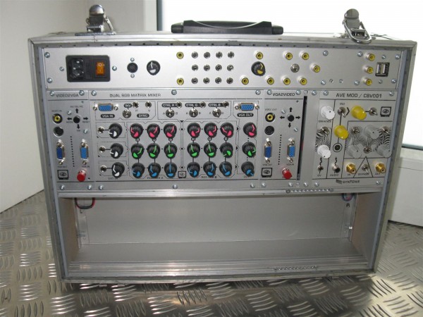
Modular Video Synth Case
PHOBoS wrote:
When I was experimenting with the video converters I realized that it was possible to add a lot of modulation options and although my
initial idea was to make it into a standalone device it made more sense now to do it modular and add things later. I was still waiting
for some parts for the converters so the modified archer enhancer was the first module I build (didn't even have a case yet).
so, I needed a case.
I wanted something that I could easily stash away since I really don't have enough space to make it part of fixed setup.
I've noticed before that the 84HP rack rails I use fit nicely in a metal* suitcase, (*actually they're made of hardboard with a thin metal plating)
so that seemed like a very suitable option and saved me some work as I didn't have to build an enclosure from scratch.
As a bonus the metal plating can work as RF shielding, though now that I think about it I am not sure if I actually connected it to anything yet.
I used 6mm MDF to make 2 side panels so I had something to mount the rails on which makes a perfect fit for the case. The foam lining inside
the case holds it firmly in place so it won't fall out but it's still easy to remove. There is enough space for 2 rows of 3U (I am using the eurorack
standard for panels) and that leaves some extra space. I wanted to have the powersupply inside the case but since the case is rather shallow
I couldn't mount it on the bottom as that would not leave enough space for most modules. The extra room that was left was just big enough
for some switched mode powersupplies which might not be the best idea for video but worth trying. I did find a nice compact 12VAC transformer
for halogen lights later so if I do run into noise issues I could probably fit that in the same space.
The power supplies had to be mounted onto something and for this I used a thin aluminium sheet that I managed to bend into the correct shape.
Initially I was planning on making a single bend and cut the remaining part off, but by adding another bend instead I got a nice U-shape that
also covers part of the bottom. I quite liked how it looked so bend another sheet to add a cover to the other side aswell. With that it's almost
completely covered without the suitcase, apart from a section on the bottom which I might cover up later.
Inspired by some of the intelijel eurorack cases I decided to add some simple circuits to the top section that has the powersupplies.
There wasn't a lot of space left but I managed to get some things in there. From left to right:
S-Video to CVBS (composite) converter with 2 outputs, 4x 1to2 passive multiples (chained so can be used as 1x 1to8 or 2x 1to4 etc),
a "dirty mixer" which is just a potentiometer with 3 connectors, a switch that can be used as a bypass switch or to select between 2
video sources, a 1to3 CVBS splitter/amplifier and 2 USB sockets to power 5V devices. I also have a gooseneck LED light that I can
plug in there. (I'll post some more info on the circuits later)
For the power connectors I didn't use the standard boxed header connectors because I want to use some thicker cable for some modules.
I'll probably make some changes to that as I have designed a couple of PCBs for video modules that do use the standard 2x8 connectors.
I know there are different connectors that don't use a ribbon cable that should also fit, so maybe I use some of those if I can find them.
Video Synth Case - 01.jpg
Description:
Filesize:
288.04 KB
Viewed:
235 Time(s)
This image has been reduced to fit the page. Click on it to enlarge.
Video Synth Case - 04.jpg
Description:
Filesize:
310.61 KB
Viewed:
252 Time(s)
This image has been reduced to fit the page. Click on it to enlarge.
Video Synth Case - 08.jpg
Description:
Filesize:
224.54 KB
Viewed:
262 Time(s)
This image has been reduced to fit the page. Click on it to enlarge.
Video Synth Case - 11.jpg
Description:
Filesize:
259.61 KB
Viewed:
254 Time(s)
This image has been reduced to fit the page. Click on it to enlarge.
Joined: Jan 14, 2010 Posts: 5950 Location: Moon Base
Audio files: 709
Posted: Mon Jun 06, 2022 10:50 am Post subject:
a recent video experiment recorded shortly after I finsihed modifying a SIMA EDIT2 video enhancer.
The main thing going on here is actually video feedback created with a Roland EDIROL V-4 videomixer
but this time I did things slightly different than what I've tried before.
setup was as follows:
-------------------------
The input was a camera connected to the EDIT2 which has CV inputs and with certain settings those can be used
to control the amount of glitching. This is what make sit look like the video is breaking apart into bits.
The output from the EDIT2 was connected to one channel of the V-4 videomixer and I used it to apply a mirroring
and colorizing effect.
The other channel of the videomixer was directly connected to its output to create a feedback loop.
To this channel I applied a chroma invert so every time the signal loops around this gets inverted,
creating the alternating colored patterns.
I also applied a fast strobe effect which basically reduces the frame rate and the result is similar to a S&H.
What I did different this time is that I mixed the 2 channels by applying a black luma key to the feedback channel,
I usually apply it to the soure channel. This luma key removes all the dark bits and replaces it with the other channel
and combined with the strobing this creates some very nice trailing effects.
The audio was added in post and is a mix of audio created by Muied Lumens with some added effects. I know it's a bit
short but it was already late and I quickly wanted to record something with the settings I had as I don't know if I can
get them back. It looks MUCH better before going through my capture device btw, especially on my CRT TV. _________________ "My perf, it's full of holes!" http://phobos.000space.com/ SoundCloudBandCampMixCloudStickney SynthyardsCaptain ColliderTwitchYouTube
Joined: Jan 14, 2010 Posts: 5950 Location: Moon Base
Audio files: 709
Posted: Mon Jun 06, 2022 1:40 pm Post subject:
SIMA Edit 2
The Sima Edit 2 is a standard video enhancer very similar to the archer video enhancer and a couple of others.
I am not exactly sure what's going on but it can add a bit of sharpness/brightness/color to the signal and has just a
signal control. It mostly seems to be some amplification and filtering. Important to note is that it does not create
a video signal by itself, it is only able to process one. If you would feed it garbage it's not going to magically turn
it into a nice valid video signal. It has an audio mixer section (which is the main difference with the Edit 1) and
can switch between 2 inputs. I also has a true bypass switch and a button for fading to/from black.
Before modifying it by probing around and seeing what happens if you connect points together (aka circuit bending)
I wanted to have some idea of what the circuit actually looks like and since I couldn't find any schematics online I had
to reverse engineer it. It has 2 large PCBs and a couple of smaller once but one of those only has a couple of connectors
and the other some extra circuitry (preamp ?) for the mic input which I don't really care about. I also didn't really care
about the audio mixer, which seemed to have a pretty standard setup with opamps, nor the auto-fade circuit.
The video section has 2 chips of which the numbers have been ground off so I don't know what they are
but one of them is likely a comparator for sync extraction. Since the other one is controlled by this chip it has probably
something to do with re-generating the blanking/sync signal. What's interesting is that poking around that chip can
have the effect of shifting the total image horizontally or shift just one of the interlaced frames.
To get started with the modifications I found a usefull tip in this video which mentions using the output signal and
try to connect it to other points in the circuit, ie. create feedback loops and if you look at the schematics that is one of
the main things I did. I did alter the output a little bit and added a seperate output resistor to have somewhat of an
isolated path to create a little bit of extra protection to whatever I connect the output too. I also added a diode and a
resistor to the main output as a crude voltage limiter for more protection.
Then the eleborate process began of poking around in the circuit, using resistors/pots/capacitors/inductors to connect
points together trying to create interesting results. There was a little bit of logic involved by looking at the schematic
to know what might be interesting and what to avoid but most of it is just trial and error.
After a lot of testing I decided to stop while I was ahead as things were started to get messy and confusing and the chance of
maybe breaking something grew larger. There are probably a lot more interesting things to do with it and I do have an Edit 1
to play around with in the future. CV control was a last minute addition and optocouplers aren't ideal for it but I got some nice
effects with them. I added 2 simple envelope followers which are connected to the internal mixer so I can use the audio inputs
of the Edit 2 for that.
To make the connection between the circuit boards and the pots/switches I used a ribbon cable which did make wiring a lot easier.
I believe it all worked on the first try but with something like this it is a bit hard to tell if it works as it should. At least everything
has an effect and I get similar results to when it was on breadboard.
The schematics aren't complete and there might be different versions of the Edit 2, eg an NTSC version with different component
values, but maybe they can be helpful to get started doing something similar.
SIMA EDIT 2 - main board mods.gif
Description:
Filesize:
178.32 KB
Viewed:
304 Time(s)
This image has been reduced to fit the page. Click on it to enlarge.
SIMA EDIT 2 - enhance circuit.gif
Description:
the 2 x's indicate bend points that I found later for a similar enhancer and want to try on the Edit 1
Filesize:
70.14 KB
Viewed:
307 Time(s)
This image has been reduced to fit the page. Click on it to enlarge.
SIMA edit2 - WIP [20220108].jpg
Description:
Filesize:
311.49 KB
Viewed:
251 Time(s)
This image has been reduced to fit the page. Click on it to enlarge.
SIMA edit2 - test2 [20220108].jpg
Description:
shift effect
Filesize:
101.56 KB
Viewed:
240 Time(s)
This image has been reduced to fit the page. Click on it to enlarge.
when_the_glitch_hits.png
Description:
Filesize:
1.63 MB
Viewed:
296 Time(s)
This image has been reduced to fit the page. Click on it to enlarge.
You cannot post new topics in this forum You cannot reply to topics in this forum You cannot edit your posts in this forum You cannot delete your posts in this forum You cannot vote in polls in this forum You cannot attach files in this forum You can download files in this forum

 Forum index » DIY Hardware and Software » Stickney Synthyards


![VGA TEST BOARD [400x600].gif](phpbb-files/thumbs/t_vga_test_board_400x600_128.gif)


 so I don't know what they are


![SIMA edit2 - WIP [20220108].jpg](phpbb-files/thumbs/t_sima_edit2__wip_20220108_696.jpg)
![SIMA edit2 - test2 [20220108].jpg](phpbb-files/thumbs/t_sima_edit2__test2_20220108_557.jpg)
