| Author |
Message |
floating-water
Joined: Oct 06, 2020
Posts: 62
Location: UK
|
 Posted: Wed May 31, 2023 6:32 am Post subject:
PT2399 issues going from breadboard to PCB Posted: Wed May 31, 2023 6:32 am Post subject:
PT2399 issues going from breadboard to PCB
Subject description: having issues setting a PT2399 circuit to PCB |
  |
|
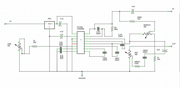
I've had this barbaric pt2399 circuit on my breadboard (it works perfectly (for my purpose) on the breadboard) for a while and have been trying to get it to PCB form so I can use it in projects however it never seems to work.
I have mapped it out on Fritzing:
My first attempt, I tried drawing it in on the schematic tab and autorouted. This design had output but it was completely clean, the knobs were basically doing nothing and no delay/effect.
Please see ATTEMPT 1 screenshots of the schematic and the autorouted pcb layout. I coudn't embed an image.
This latest attempt, I routed it on the breadboard tab, basically just following what I see on my breadboard and autorouted. This one I can hear very faintly the delay but the repeats and volume controls are a mess and the circuit is basically useless.
Please see ATTEMPT 2 screenshots of the schematic and the autorouted pcb layout. I couldn't embed an image.
I am not heavily educated on electronics, I just learn online and plug things in and see what happens. I am assuming I am making some classic mistakes, may be to do with how you should assemble components around the pt2399/autorouting not suitable.
Could someone help/shed wisdom?
Thank you.
| Description: |
|
| Filesize: |
138.73 KB |
| Viewed: |
4105 Time(s) |

|
| Description: |
|
| Filesize: |
141.43 KB |
| Viewed: |
4104 Time(s) |

|
| Description: |
|
| Filesize: |
78.75 KB |
| Viewed: |
176 Time(s) |
| This image has been reduced to fit the page. Click on it to enlarge. |

|
| Description: |
|
| Filesize: |
81.83 KB |
| Viewed: |
163 Time(s) |
| This image has been reduced to fit the page. Click on it to enlarge. |

|
|
|
|
Back to top
|
|
 |
Grumble

Joined: Nov 23, 2015
Posts: 1313
Location: Netherlands
Audio files: 30
|
| Posted: Wed May 31, 2023 7:12 am Post subject:
|
|
|
On both the schematic pictures the 5 volt coming from the regulator isn’t going anywhere but to +pin of the 47uF capacitor.
_________________
my synth |
|
|
Back to top
|
|
|
floating-water
Joined: Oct 06, 2020
Posts: 62
Location: UK
|
| Posted: Wed May 31, 2023 8:33 am Post subject:
|
|
|
Ahh OK, I'll look into that when I get home, cheers grumble.
As another note, do you think the potentiometers are wired correctly, doing some searching, Fritzing potentiometers might be set up not how they seem. As in lug '3' may be the middle lug, I assumed it was the 3rd one going ---> that way if turning it.
We'd be talking about the schematic version. |
|
|
Back to top
|
|
|
Grumble
Joined: Nov 23, 2015
Posts: 1313
Location: Netherlands
Audio files: 30
|
| Posted: Wed May 31, 2023 10:05 am Post subject:
|
|
|
In the drawing named ATTEMPT 2 - BREADBOARD CIRCUIT PCB LAYOUT.png (top drawing) the potmeters are differently drawn as in the lower drawings.
The middle pin of the potmeters are the wiper of the potmeter, between the left and right pin you should measure the total value of the potmeter, regardless of the position of the wiper.
As a sidenote: I can’t imagine why anyone should place a 10uF capacitor in series with a 100nF capacitor… so there is something wrong as well…
_________________
my synth |
|
|
Back to top
|
|
|
floating-water
Joined: Oct 06, 2020
Posts: 62
Location: UK
|
|
|
Back to top
|
|
|
floating-water
Joined: Oct 06, 2020
Posts: 62
Location: UK
|
|
|
Back to top
|
|
|
Grumble
Joined: Nov 23, 2015
Posts: 1313
Location: Netherlands
Audio files: 30
|
| Posted: Wed May 31, 2023 12:00 pm Post subject:
|
|
|
Problem is, I'm not at home and won't be for at least a month, so I'm doing this on my smartphone.
So I hope that another forum membet will chip in...
_________________
my synth |
|
|
Back to top
|
|
|
Steveg

Joined: Apr 23, 2015
Posts: 184
Location: Perth, Australia
|
| Posted: Thu Jun 01, 2023 5:54 am Post subject:
|
|
|
| Outside my area of experience so I'm not truly able to help. But looking at the circuits here might help: https://sound-au.com/project26a.htm |
|
|
Back to top
|
|
|
floating-water
Joined: Oct 06, 2020
Posts: 62
Location: UK
|
| Posted: Thu Jun 01, 2023 7:58 am Post subject:
|
|
|
No worries grumble and thanks Steveg for that link, the information on there looks good to compare to. I just got to get stuck into the breadboard but I'm away for the weekend now.
Please, if anyone is able to offer anything else I'd be so grateful. |
|
|
Back to top
|
|
|
floating-water
Joined: Oct 06, 2020
Posts: 62
Location: UK
|
| Posted: Sun Jul 02, 2023 9:59 am Post subject:
|
|
|
@Grumble, would you be available to run through the circuit now if you are back?
Thanks |
|
|
Back to top
|
|
|
The Peasant

Joined: Nov 13, 2009
Posts: 112
Location: Sunny Alberta
Audio files: 1
|
|
|
Back to top
|
|
|
|

 Forum index » DIY Hardware and Software