| Author |
Message |
Uncle Krunkus
Moderator

Joined: Jul 11, 2005
Posts: 4761
Location: Sydney, Australia
Audio files: 52
G2 patch files: 1
|
 Posted: Mon Aug 04, 2008 7:19 pm Post subject:
LM386 E-Bow Experiments Posted: Mon Aug 04, 2008 7:19 pm Post subject:
LM386 E-Bow Experiments
Subject description: Here's a picture of the "apparatus" |
  |
|
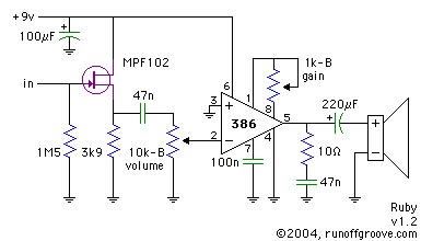
I've started doing some experiments with the LM386 as a coil driver like in an e-bow. I've attached the schem for the e-bow and for the ruby amp for reference.
One thing I don't understand is that I can only get the e-bow to work (ie set up an oscillation in a guitar string), if I use the 500R side of the transformer. The schem looks very similar to the Ruby Amp which is driving an 8R speaker. So why the difference?
When I connect it to the 8R side of the transformer the LM386 seems to self oscillate at a sub sonic frequency regardless of input.
BTW Does anybody know what a "telephone pick-up" is? It's impedance? mV out?
| Description: |
|
| Filesize: |
3.7 KB |
| Viewed: |
48597 Time(s) |
|
| Description: |
|
| Filesize: |
15.4 KB |
| Viewed: |
48597 Time(s) |
|
_________________
What makes a space ours, is what we put there, and what we do there.
Last edited by Uncle Krunkus on Tue Aug 12, 2008 7:49 am; edited 2 times in total |
|
|
Back to top
|
|
 |
widdly
Joined: Jun 25, 2007
Posts: 268
Location: singapore
G2 patch files: 2
|
| Posted: Mon Aug 04, 2008 9:35 pm Post subject:
|
|
|
Maybe a carbon microphone? They were used in old telephones.
You might have one in an old rotary dial telephone in your shed. (technically still the property of "telecom" but they probably don't need it back) 
This guy makes mics from them.
http://www.myspace.com/carbonmicrophone
Apparently you can use them to make electro-mechanical amplifiers 
http://www.dself.dsl.pipex.com/MUSEUM/COMMS/mechamp/mechamp.htm#ha
Last edited by widdly on Thu Aug 05, 2010 10:09 pm; edited 1 time in total |
|
|
Back to top
|
|
|
CJ Miller

Joined: Jan 07, 2007
Posts: 368
Location: 127.0.0.1
|
| Posted: Tue Aug 05, 2008 3:02 am Post subject:
Re: LM386 E-Bow Experiments |
|
|
| Uncle Krunkus wrote: | | BTW Does anybody know what a "telephone pick-up" is? It's impedance? mV out? |
A "telephone pickup" is not a microphone, but rather an induction coil used to record phone calls. I used to see them in Radio Shack, they might still sell them. Black plastic case with a suction cup on one side, and a cable coming out the other, usually terminating in a 1/8" mono plug. You could stick it near the earpiece and record without needing to open the phone or wiring audio transformers into the line.
I think I have one lost in boxes of junk somewhere, but sorry I've got no stats nor measurements.
Sounds like an interesting project! |
|
|
Back to top
|
|
|
Uncle Krunkus
Moderator
Joined: Jul 11, 2005
Posts: 4761
Location: Sydney, Australia
Audio files: 52
G2 patch files: 1
|
| Posted: Tue Aug 05, 2008 5:32 am Post subject:
Re: LM386 E-Bow Experiments |
|
|
| CJ Miller wrote: | | Sounds like an interesting project! |
Oh,... you have no idea! 
The "project" involves using the e-bow type transducers to pump a vibration into a "dream catcher" type construction made of soldered guitar strings. Then I'd like to use another two transformers to extract the mechanical resonance which is set up. I figure that if I build some deadening fingers into the structure, I should be able to reduce the "twangyness" of an overbearing resonance. The output will of course include a couple of parametric EQs to carve the effect a bit. It won't sound anything like a spring reverb, but I'm glad of that. It will have a stereo in/out because of the four transducers.
I'm thinking I might call it a Dissonator.
I've already got an input vibrating the web, and the output off one other transducer producing about 60mV p-p.
The best thing is the entire assembly fits on a 34*34 hole square piece of stripboard, so once I get it fine tuned, it will be possible to put one into a modular format. And,..... the "web" simply screws onto the four corner posts, so you can try soldering up a different "pattern" and testing it on the same board.
_________________
What makes a space ours, is what we put there, and what we do there.
Last edited by Uncle Krunkus on Tue Aug 05, 2008 8:18 am; edited 1 time in total |
|
|
Back to top
|
|
|
blue hell
Site Admin

Joined: Apr 03, 2004
Posts: 24499
Location: The Netherlands, Enschede
Audio files: 298
G2 patch files: 320
|
| Posted: Tue Aug 05, 2008 5:37 am Post subject:
Re: LM386 E-Bow Experiments |
|
|
| Uncle Krunkus wrote: | | So why the difference? |
The transformer is more inductive as it has more windings than a typical speaker. Amplifiers tend to not like inductive loads and the 47n / 10E network is present to compensate which is needed even for a speaker load. Now the 500 E winding would have even more inductance, but also more resistance (the Q factor is lower, the wire not as thick), so probably that one behaves more like a resistive load. It's good to keep an eye on the amplifier, inductive loads are capable of killing amps. As long as it doesn't run too hot you'll be OK likely, but also check it with a scope to see if you have funny oscillations on the output (as you already did I see now).
_________________
Jan
also .. could someone please turn down the thermostat a bit.
 |
|
|
Back to top
|
|
|
Uncle Krunkus
Moderator
Joined: Jul 11, 2005
Posts: 4761
Location: Sydney, Australia
Audio files: 52
G2 patch files: 1
|
| Posted: Tue Aug 05, 2008 7:39 am Post subject:
|
|
|
Thanks Jan,
Yeah the output looks a bit "spikey", I assumed that was because of the back EMF from the transformer adding to the alternately swinging drive current. (That sounds more impressive than my understanding is! )
Okay, so I need to use the 500R side whether I'm going in or out. I'm adding tiny rare earth magnets which are held on the ends of the "springs". They definitely up the input transducers effect, (2-3mm of vibration on a "spring" which is only 35mm long!) and I figured they would be the only way of getting anything out.
Now I just need to look at the amplifying of the output. I'm thinking I'll just run straight into a high gain op-amp, that should allow up to 5-10V p-p hey?
Then I need to do some impulse testing, and see if I can tweak the "web" to be a little less predictable in the way it reacts to various inputs. Maybe even build another couple with differing "stiffness" and see how that goes.
There should some pics, and possibly even a sound sample soon! 
_________________
What makes a space ours, is what we put there, and what we do there. |
|
|
Back to top
|
|
|
Uncle Krunkus
Moderator
Joined: Jul 11, 2005
Posts: 4761
Location: Sydney, Australia
Audio files: 52
G2 patch files: 1
|
| Posted: Tue Aug 05, 2008 7:59 pm Post subject:
|
|
|
Hey! Guess what!
Don't ever try running an LM386 off 15V!!
Well,... I did have the polarity reversed and that might have compounded the "Where's that smell coming from?" effect.
Okay maybe it'd be okay on 15V if you wire the power the right way round.
We all do a bit of remedial circuit analysis from time to time!
BTW It turns out that the datasheet says 15V is absolute max, so I'm not surprised it was a bit touchy about which way it came in!
_________________
What makes a space ours, is what we put there, and what we do there. |
|
|
Back to top
|
|
|
slabman
Joined: Sep 01, 2005
Posts: 102
Location: UK
|
| Posted: Wed Aug 06, 2008 7:55 am Post subject:
Cross-coupling |
|
|
| There's always a danger that some of the magnetic field from the drivers gets picked up directly by the pickups, bypassing the mechanical bits. So, it might be worth considering magnetic drivers and piezo pickups - or vice-versa |
|
|
Back to top
|
|
|
fluxmonkey
Joined: Jun 24, 2005
Posts: 708
Location: cleve
|
| Posted: Wed Aug 06, 2008 8:30 am Post subject:
|
|
|
there is a variant LM386N-4 part that is rated to 22v.
| Uncle Krunkus wrote: | Hey! Guess what!
Don't ever try running an LM386 off 15V!!
Well,... I did have the polarity reversed and that might have compounded the "Where's that smell coming from?" effect.
Okay maybe it'd be okay on 15V if you wire the power the right way round.
We all do a bit of remedial circuit analysis from time to time!
BTW It turns out that the datasheet says 15V is absolute max, so I'm not surprised it was a bit touchy about which way it came in! |
_________________
www.fluxmonkey.com |
|
|
Back to top
|
|
|
Uncle Krunkus
Moderator
Joined: Jul 11, 2005
Posts: 4761
Location: Sydney, Australia
Audio files: 52
G2 patch files: 1
|
| Posted: Thu Aug 07, 2008 3:16 am Post subject:
Re: Cross-coupling |
|
|
| slabman wrote: | | There's always a danger that some of the magnetic field from the drivers gets picked up directly by the pickups, bypassing the mechanical bits. So, it might be worth considering magnetic drivers and piezo pickups - or vice-versa |
Yeah, I thought about this, and I might try piezo pickups as well, although I must admit that I'm not particularly worried about the whole thing just becoming a mess of resonating flux. That kind of chaos/distortion/contamination is what I'm after. It could be good to try piezos though if things get too out of control. It would be very easy to modify it for piezo pickups, I'd basically just bend one of the guitar strings down so that it touches the middle of a piezo pickup. It would also be a good way of automatically and mechanically removing the low frequency resonances, as piezos don't go down that far.
_________________
What makes a space ours, is what we put there, and what we do there. |
|
|
Back to top
|
|
|
elektro80
Site Admin

Joined: Mar 25, 2003
Posts: 21959
Location: Norway
Audio files: 14
|
| Posted: Thu Aug 07, 2008 3:22 am Post subject:
|
|
|
e-bow
I suddenly remembered that an old friend of mine modded or rebuilt or cloned an ebow some years ago and supposedly one of the things he added was midi control of the magnetic/exciter field thingie. Actually, he could sequence rythmic patterns and the borg / e-bow device would make the string go oyoyoyoyoyoywheeeewheeewheeehuhuhuhuhu and so forth
_________________
A Charity Pantomime in aid of Paranoid Schizophrenics descended into chaos yesterday when someone shouted, "He's behind you!"
MySpace
SoundCloud
Flickr |
|
|
Back to top
|
|
|
Uncle Krunkus
Moderator
Joined: Jul 11, 2005
Posts: 4761
Location: Sydney, Australia
Audio files: 52
G2 patch files: 1
|
| Posted: Thu Aug 07, 2008 5:45 am Post subject:
|
|
|
Yeah I can imagine there's heaps you could do with pulsed inversion, pulsed frequency doubling, halving, etc. Extracting enough timing information from the midi chain to make it effective wouldn't actually be very hard either. Still, it would be way above my ability at this stage.
I'll have to put these experiments on hold for a day though, as it's my birthday tomorrow, and there's a big celebration happening with parades and fireworks and everything!! The only problem is that the organisers stuffed up the venue!! It's not happening in Nambucca Heads at all!! They got mixed up and organised it all to go off in Beijing!! I s'pose that's birthday parties after 40 for you. Complete balls up!!
_________________
What makes a space ours, is what we put there, and what we do there. |
|
|
Back to top
|
|
|
blue hell
Site Admin
Joined: Apr 03, 2004
Posts: 24499
Location: The Netherlands, Enschede
Audio files: 298
G2 patch files: 320
|
| Posted: Thu Aug 07, 2008 8:10 am Post subject:
|
|
|
have a good day with all that &
 
_________________
Jan
also .. could someone please turn down the thermostat a bit.
|
|
|
Back to top
|
|
|
Uncle Krunkus
Moderator
Joined: Jul 11, 2005
Posts: 4761
Location: Sydney, Australia
Audio files: 52
G2 patch files: 1
|
| Posted: Thu Aug 07, 2008 4:16 pm Post subject:
|
|
|
Thanks Jan!
_________________
What makes a space ours, is what we put there, and what we do there. |
|
|
Back to top
|
|
|
elektro80
Site Admin
Joined: Mar 25, 2003
Posts: 21959
Location: Norway
Audio files: 14
|
| Posted: Thu Aug 07, 2008 4:23 pm Post subject:
|
|
|
and remember the  and and 
_________________
A Charity Pantomime in aid of Paranoid Schizophrenics descended into chaos yesterday when someone shouted, "He's behind you!"
MySpace
SoundCloud
Flickr |
|
|
Back to top
|
|
|
Uncle Krunkus
Moderator
Joined: Jul 11, 2005
Posts: 4761
Location: Sydney, Australia
Audio files: 52
G2 patch files: 1
|
| Posted: Thu Aug 07, 2008 4:33 pm Post subject:
|
|
|
I've got my best friend from school coming up from Sydney, Felicity's brother coming down from Brisbane, and a good friend I've made here in Nambucca, all coming over for a BBQ, and later we're gonna light a campfire and chuck some bamboo bangers on! We will of course be doused in numerous libations!!
_________________
What makes a space ours, is what we put there, and what we do there. |
|
|
Back to top
|
|
|
Luka

Joined: Jun 29, 2007
Posts: 1003
Location: Melb.
|
|
|
Back to top
|
|
|
beavis
Joined: Aug 23, 2007
Posts: 14
Location: US
|
| Posted: Fri Aug 08, 2008 9:58 am Post subject:
|
|
|
I can't speak to the coil issue, but there are a few 386-related things you can try.
1. You can increase gain a bit by connecting pins 1 and 8 together and then connecting that to a 100ohm and 4.7uf cap in series to ground, sort of like this: http://beavisaudio.com/Projects/ArmageddonProcessor/index.6.jpg
2. Since you are driving an actual speaker, you could probably drop the zoebel network off the end (i.e. drop the 47n/10 ohm to ground).
3. I've done a lot of 386 based stuff and have found that in almost all cases the JRC/NJM version of the chip is more stable.
4. Off pin 7, I almost always use a 100nf to ground for stability.
FWIW, and good luck with the project.
_________________
www.beavisaudio.com |
|
|
Back to top
|
|
|
Scott Stites
Janitor


Joined: Dec 23, 2005
Posts: 4127
Location: Mount Hope, KS USA
Audio files: 96
|
| Posted: Fri Aug 08, 2008 1:21 pm Post subject:
|
|
|
Happy Berfday, Unca K
_________________
My Site |
|
|
Back to top
|
|
|
Uncle Krunkus
Moderator
Joined: Jul 11, 2005
Posts: 4761
Location: Sydney, Australia
Audio files: 52
G2 patch files: 1
|
| Posted: Sat Aug 09, 2008 9:31 pm Post subject:
|
|
|
| beavis wrote: | | 2. Since you are driving an actual speaker, you could probably drop the zoebel network off the end (i.e. drop the 47n/10 ohm to ground). |
Since you are or since you aren't?
Cos I'm not, driving an actual speaker. It's driving the 500R side (CT) of a 450mW output transformer, but there's nothing on the 8R output winding.
Thanks for the ideas beavis.
While we're at it:-
What does a Zoebel network do exactly?
Can I control the frequency response by varying the 220uF on the output?
How much input signal is too much? For example, when I open up the attenuator pot I put across the input (B10K) and then put say a 2Vp-p sinewave in, the trace shows an obvious clipping across the output.
_________________
What makes a space ours, is what we put there, and what we do there. |
|
|
Back to top
|
|
|
beavis
Joined: Aug 23, 2007
Posts: 14
Location: US
|
| Posted: Sun Aug 10, 2008 6:16 am Post subject:
|
|
|
| Uncle Krunkus wrote: | | beavis wrote: | | 2. Since you are driving an actual speaker, you could probably drop the zoebel network off the end (i.e. drop the 47n/10 ohm to ground). |
Since you are or since you aren't?
Cos I'm not, driving an actual speaker. It's driving the 500R side (CT) of a 450mW output transformer, but there's nothing on the 8R output winding.
Thanks for the ideas beavis.
While we're at it:-
What does a Zoebel network do exactly?
Can I control the frequency response by varying the 220uF on the output?
How much input signal is too much? For example, when I open up the attenuator pot I put across the input (B10K) and then put say a 2Vp-p sinewave in, the trace shows an obvious clipping across the output. |
Right, since you *aren't* driving a speaker. 
Zoebel network: a fancy name for a filter: http://en.wikipedia.org/wiki/Zobel_network
I think you could control frequency response, but I would leave the 220uf output cap in place. What I would do is a low pass filter either before the input, or for more fun, splice it into the 386's feedback loop, right between pins 1 and 8.
Almost all the stuff I've done with the 386 is for guitar, and my pickups rarely put out more than 1v P2P. So I actually strive to boost the signal to get as much distortion as possible, probably the reverse of what you are trying to accomplish . If you use the N4 version of the LM386 chip, you can theoretically drive it up to 18 volts if memory serves me. That should give you more headroom before you start clipping.
_________________
www.beavisaudio.com |
|
|
Back to top
|
|
|
Uncle Krunkus
Moderator
Joined: Jul 11, 2005
Posts: 4761
Location: Sydney, Australia
Audio files: 52
G2 patch files: 1
|
| Posted: Sun Aug 10, 2008 4:05 pm Post subject:
|
|
|
| beavis wrote: | | Zoebel network: a fancy name for a filter |
Okay, so, what you're saying is that because I'm not driving an actual speaker, I could maybe do away with the Zoebel network. The Zoebel network is acting to equalise the impedance presented to the amp regardless of the frequency which the speaker is reacting to, yeah? Or in other words, it's minimising the drop in impedance around the resonant frequency of the equivalent LR circuit of the speaker. Which is very interesting, as the effective L of the speaker (or transformer in my case) will change depending on a number of physical factors as well, yeah? Like the strength of the magnet, the dampening in the cone, the resonant frequency of the enclosure, etc.
The reason I'm thinking this out loud is that my most important consideration at this stage is how to reduce the fundamental resonant frequency of my "web", in order to minimise standing waves taking over completely. It's actually the higher frequency resonances I really want. So where you said I could maybe use a low pass filter in the input or across pins 1&8, I actually want a high pass. Know what I mean?
So understanding the Zoebel network could be crucial to getting the best energy transfer into the "web" without allowing it to settle into it's most prominent resonance. For example, if I find the fundamental resonance of the web, I could tweak the Zoebel network to greatly increase the effective impedance at that frequency, which should equalise the driving force from the transformer.
It would be very handy if I could find out what the inductance of my modified transformer primary is hey? Keep in mind I've disassembled the core and put all the E peices back but not the I's. Or should I ignore that and just work off what I can measure as the overiding resonant frequency of the transformer/magnet/and web is?
Thanks heaps Beavis for this bit of theory before I get into any more experimentation. I really helps clarify what I'm trying to do, and what are the important considerations.
_________________
What makes a space ours, is what we put there, and what we do there. |
|
|
Back to top
|
|
|
Uncle Krunkus
Moderator
Joined: Jul 11, 2005
Posts: 4761
Location: Sydney, Australia
Audio files: 52
G2 patch files: 1
|
Posted: Mon Aug 11, 2008 6:39 pm Post subject:
Piezo's
Subject description: Piezo's |
|
|
Okay,
I think I now need to get some decent outputs happening, and I've decided to go with slabman's advice and use piezo's for the outputs.
How should I pre-amp them? I was thinking of the loading with a few 10M resistors, then into a 10X inverting stage TL07X kind of setup, similar to what Ray uses in the SoundLab drum trigger. Are there any better ways? I may want to mix in the original, maybe not, depends what I find!!
I'm going to diametrically oppose the inputs and outputs so that the inputs are in opposite corners and the same for the outputs. Once I get the parts laid out on the board I'll post a pic.
_________________
What makes a space ours, is what we put there, and what we do there. |
|
|
Back to top
|
|
|
Uncle Krunkus
Moderator
Joined: Jul 11, 2005
Posts: 4761
Location: Sydney, Australia
Audio files: 52
G2 patch files: 1
|
|
|
Back to top
|
|
|
blue hell
Site Admin
Joined: Apr 03, 2004
Posts: 24499
Location: The Netherlands, Enschede
Audio files: 298
G2 patch files: 320
|
| Posted: Tue Aug 12, 2008 9:08 am Post subject:
|
|
|
Righto, that's what you meant all the time - I had much longer strings in mind So what does it sound like? I'll wait for the preamps and extra wires
_________________
Jan
also .. could someone please turn down the thermostat a bit.
|
|
|
Back to top
|
|
|
|

 Forum index » DIY Hardware and Software

