| Author |
Message |
Inventor
Stream Operator

Joined: Oct 13, 2007
Posts: 6221
Location: near Austin, Tx, USA
Audio files: 267
|
 Posted: Sun May 17, 2009 3:42 pm Post subject:
Peace, Love, and LEDs Posted: Sun May 17, 2009 3:42 pm Post subject:
Peace, Love, and LEDs
Subject description: An interesting project for my hippie mom |
  |
|
Mom wants me to make a circuit board that is a peace sign with white LEDs on it. I'm posting to Schmooze because it's not a music project and i feel very Schmoozy on this lazy Sunday afternoon.
She drew a 6" peace sign in the air with her finger and said to make it with white lights. Also to make it play hippie music if possible. She says with the new trend in 60's revival it will sell like hotcakes, but i'd just like for her to have one.
So I'm thinking of doing yet another project, a circuit board that's routed into a peace sign with dozens of LEDs on it. Maybe even with a solar cell behind it and a battery so it charges during the day and lights up all night.
I dunno, mom suggested it so I thought I would schmooze away. What do you think?
_________________
"Let's make noise for peace." - Kijjaz |
|
|
Back to top
|
|
 |
Rykhaard
Joined: Sep 02, 2007
Posts: 1290
Location: Canada
|
| Posted: Sun May 17, 2009 3:52 pm Post subject:
|
|
|
Will the LEDs be cycling in any way, or no?
White LEDs only? I myself being an LED phreak, would prefer tri-colour LEDs. Each of the colours, or sections of each colour in the LEDs, could be driven by different clock combinations.
What I've done in the past for my tri-colour LED / wind chime invention (only 1 ever built) was have 6 x CD40106 clocks. For each of the 3 x tri-colour LEDs, was drive each of their 9 colours, with 4 combinations of the 6 available clocks. The summed square wave outputs were slewed (via caps) to soften their turn on / off times.
This presented an absolutely wild combination of ever changing colours, when any of the 6 wind chimes, made connection with their respective busses, to light which ever colours within whichever of the 3 tri-colour LEDs. (I've a video somewhere on my system; possibly at my youtube site as well.)
That - to me - in a peace sign, would be friggin' WILD!  (I did the same thing inside of a kitchen ceiling lamp enclosure for a friend / neighbour of ours, with a total of 20 different LEDs. A few of them were tri-colours. Has it mounted in his rec room and for the first few months that he had it, he'd just sit in the couch, listening to tunes, freakin' out at the light show. (I did the same thing inside of a kitchen ceiling lamp enclosure for a friend / neighbour of ours, with a total of 20 different LEDs. A few of them were tri-colours. Has it mounted in his rec room and for the first few months that he had it, he'd just sit in the couch, listening to tunes, freakin' out at the light show.  Oh yeah - something very similar to this such, will be going in behind the frosted plexiglass back panel of my current noise machine. The tri-colours will be driven by different portions of the noise machine's audio.) Oh yeah - something very similar to this such, will be going in behind the frosted plexiglass back panel of my current noise machine. The tri-colours will be driven by different portions of the noise machine's audio.) |
|
|
Back to top
|
|
|
Inventor
Stream Operator
Joined: Oct 13, 2007
Posts: 6221
Location: near Austin, Tx, USA
Audio files: 267
|
| Posted: Sun May 17, 2009 4:13 pm Post subject:
|
|
|
I am so totally psyched at your idea, Rykhaard, care to post a schematic of your LED driver circuit? Hmmm... would be kewl if the LED's were banked into groups or something, I dunno. I think this could be a great electro-music.com product if we got together and worked on it, would retail well perhaps. Then Howard would have to buy us all free beer! LOL!
_________________
"Let's make noise for peace." - Kijjaz |
|
|
Back to top
|
|
|
Inventor
Stream Operator
Joined: Oct 13, 2007
Posts: 6221
Location: near Austin, Tx, USA
Audio files: 267
|
| Posted: Sun May 17, 2009 4:20 pm Post subject:
|
|
|
Upon a moment's reflection, it occurs to me that we could put a little microphone on it and make the LEDs respond to sound somehow... Wouldn't that be kewl? Solar or battery? I think perhaps battery to keep it simple...
_________________
"Let's make noise for peace." - Kijjaz |
|
|
Back to top
|
|
|
Rykhaard
Joined: Sep 02, 2007
Posts: 1290
Location: Canada
|
| Posted: Sun May 17, 2009 4:29 pm Post subject:
|
|
|
Haha! Les - now you've RE-psyched ME about it! 
I'll have to go searching through my notebooks for the schematics. I'll have them on paper for sure and possibly in this machine. It'll just take some searching and / or scanning.
I'm all for donating the idea to EM as well. I'm not into any profit stuff myself any more. I'm just here trying to have a good time and helping others to as well.
And a mic! Yes! I HAD thought of that in the past, to make the ones interactive. Going back to the days of the 'light organ', I'd thought of taking what the mic is listening to; deriving certain frequency ranges and having THEM modify the clocks / intensities of colours / what-have-you.
I never DID do a 2nd version though. After working on the 2 light systems, I came back instead, to working on my normal modular. (Summer 2007.)
Long weekend. Just about to go watch Survivor's last episode for 3 hours. I should have time tomorrow to search out the schematics, for posting. I'm completely open to modifications / etc. |
|
|
Back to top
|
|
|
Inventor
Stream Operator
Joined: Oct 13, 2007
Posts: 6221
Location: near Austin, Tx, USA
Audio files: 267
|
| Posted: Sun May 17, 2009 4:31 pm Post subject:
|
|
|
Most excellent, my compadre! Let's work on this. Anyone else want to join us?
Les
_________________
"Let's make noise for peace." - Kijjaz |
|
|
Back to top
|
|
|
Rykhaard
Joined: Sep 02, 2007
Posts: 1290
Location: Canada
|
| Posted: Sun May 17, 2009 4:46 pm Post subject:
|
|
|
| Inventor wrote: | Most excellent, my compadre! Let's work on this. Anyone else want to join us?
Les |
Top notch! Shall do!  |
|
|
Back to top
|
|
|
cappy2112

Joined: Dec 24, 2004
Posts: 2500
Location: San Jose, California
Audio files: 2
G2 patch files: 1
|
Posted: Sun May 17, 2009 5:04 pm Post subject:
Re: Peace, Love, and LEDs
Subject description: An interesting project for my hippie mom |
|
|
| Inventor wrote: | Mom wants me to make a circuit board that is a peace sign with white LEDs on it. I'm posting to Schmooze because it's not a music project and i feel very Schmoozy on this lazy Sunday afternoon.
She drew a 6" peace sign in the air with her finger and said to make it with white lights. Also to make it play hippie music if possible. She says with the new trend in 60's revival it will sell like hotcakes, but i'd just like for her to have one.
So I'm thinking of doing yet another project, a circuit board that's routed into a peace sign with dozens of LEDs on it. Maybe even with a solar cell behind it and a battery so it charges during the day and lights up all night.
I dunno, mom suggested it so I thought I would schmooze away. What do you think? |
Timothy's LEDdies 
_________________
Free Tibet. Release the Panchen Lama from prison. Let the Dalai Lama return to his home. |
|
|
Back to top
|
|
|
Inventor
Stream Operator
Joined: Oct 13, 2007
Posts: 6221
Location: near Austin, Tx, USA
Audio files: 267
|
| Posted: Sun May 17, 2009 5:18 pm Post subject:
|
|
|
I've built some miniature condenser microphone circuits before. It takes two opamps in series because one opamp stage cannot produce enough gain, in my attempts anyway. You bias the condenser mic with a 10k resistor (if it does not have an internal resistor) and thus form a voltage divider, then you AC couple the small-signal with a 0.1 uF cap into an inverting amp with artificial ground, then AC couple into another inverting amp and you've got your audio signal. Wow, what a run-on sentence.
After that I'd imagine passive low-pass, band-pass, and high-pass filters for the three colors, followed by some type of LED driving chip that I'm not sure what it should be.
It would be best to do it all single-sided and perhaps all through-hole instead of surface mount. An important consideration is to have continuous LEDs so where do we put the microphone/driver circuitry? Not sure exactly how to do that. Ideas?
_________________
"Let's make noise for peace." - Kijjaz |
|
|
Back to top
|
|
|
seraph
Editor


Joined: Jun 21, 2003
Posts: 12398
Location: Firenze, Italy
Audio files: 33
G2 patch files: 2
|
| Posted: Mon May 18, 2009 1:37 am Post subject:
|
|
|
at first when I read the thread's title I thought it said: Peace, Love, and LSD I got bewildered for a fraction of a second 
_________________
homepage - blog - forum - youtube
| Quote: | | Don't die with your music still in you - Wayne Dyer |
|
|
|
Back to top
|
|
|
Inventor
Stream Operator
Joined: Oct 13, 2007
Posts: 6221
Location: near Austin, Tx, USA
Audio files: 267
|
| Posted: Mon May 18, 2009 11:13 am Post subject:
|
|
|
| seraph wrote: | | at first when I read the thread's title I thought it said: Peace, Love, and LSD I got bewildered for a fraction of a second |
Hehehe, those dazzling LEDs will do that to you!
_________________
"Let's make noise for peace." - Kijjaz |
|
|
Back to top
|
|
|
Inventor
Stream Operator
Joined: Oct 13, 2007
Posts: 6221
Location: near Austin, Tx, USA
Audio files: 267
|
| Posted: Tue May 19, 2009 6:24 am Post subject:
|
|
|
Hey Rych and all,
I'm feeling productive this morning (made a ChucK accelerometer tambourine and a ChucK lunetta simulation earlier) so I thought I would get started on the Eagle schematic for the peace sign. It just has the microphone and a dual inverting opamp stage using an LM324. What's next?
Les
| Description: |
| Screenshot of the schematic for your convenience |
|
| Filesize: |
75.82 KB |
| Viewed: |
240 Time(s) |
| This image has been reduced to fit the page. Click on it to enlarge. |

|
| Description: |
| Eagle Schematic of Peace Sign Microphone and amplifier |
|

Download (listen) |
| Filename: |
PeaceSign1.sch |
| Filesize: |
66.36 KB |
| Downloaded: |
170 Time(s) |
_________________
"Let's make noise for peace." - Kijjaz |
|
|
Back to top
|
|
|
Inventor
Stream Operator
Joined: Oct 13, 2007
Posts: 6221
Location: near Austin, Tx, USA
Audio files: 267
|
| Posted: Tue May 19, 2009 6:46 am Post subject:
|
|
|
Some more thoughts:
Routing out the four interior chambers would be OK, but then we have the problem of where to put the batteries, the circuitry, etc. Now I'm thinking that we would be better off leaving the whole thing unrouted except for the outer round routing cut. I mean, it's a peace sign, it should at least be round. Then the batteries can go, say, in the upper left panel and the circuitry in the upper right, with the microphone just right of center - or better put the mic at the juncition in the middle.
For filters I'm thinking that we should go with active filters perhaps. Simpler though would be an RC low pass, an RC high pass and an active band-pass or even LC band-pass. Then obviously we control the RGB intensities with those three signals.
Just doing that, however is not dazzling enough! It would just flash on and off when you talked, which is OK but I'd rather see the LEDs blink around somehow. I once worked on ring oscillator networks. You can make arbitrary networks with them, not just rings. Meshes and such. So maybe we have some delay element like a 555 or an RC followed by an invertor, then arrange them into a ring network of some sort.
We'd have to pay attention to details like making the number of LEDs in each branch a prime number or something, but we can do simulations in Spice and/or ChucK to make sure it will work before making boards.
Comments?
Les
_________________
"Let's make noise for peace." - Kijjaz |
|
|
Back to top
|
|
|
Inventor
Stream Operator
Joined: Oct 13, 2007
Posts: 6221
Location: near Austin, Tx, USA
Audio files: 267
|
| Posted: Tue May 19, 2009 12:07 pm Post subject:
|
|
|
I also just realized that using Eagle will limit us to a three inch diameter peace sign... is that OK?
_________________
"Let's make noise for peace." - Kijjaz |
|
|
Back to top
|
|
|
Inventor
Stream Operator
Joined: Oct 13, 2007
Posts: 6221
Location: near Austin, Tx, USA
Audio files: 267
|
| Posted: Tue May 19, 2009 12:50 pm Post subject:
|
|
|
Latest thoughts:
o We can vary the brightness of the LEDs with voice using current mirrors. These can be switched so that they also pulse.
o It would be kewl if we could vary the frequency of the flashing with the voice somehow. I figure using a quad of relaxation oscillators with modulation inputs would do the job. That gives us four LED blinking rates to spread around the board.
o another option that sounds perhaps better than the relaxation oscillators is to derive the blinking rate from the voice itself. One LM324 opamp in comparator configuration squares up the amplified voice, then a clock divider chip divides it down. We might have to low-pass filter the signal first or whatever.
Just some thoughts...
_________________
"Let's make noise for peace." - Kijjaz |
|
|
Back to top
|
|
|
Inventor
Stream Operator
Joined: Oct 13, 2007
Posts: 6221
Location: near Austin, Tx, USA
Audio files: 267
|
| Posted: Tue May 19, 2009 7:55 pm Post subject:
|
|
|
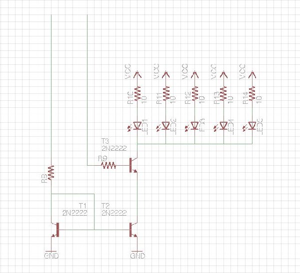
Awake after some naps and a most excellent electro-music.com radio show by Bill (State Machine) and friends, I thought I would put a little time into the peace sign project. The circuit shown below is a current mirror with a separate on/off control.
I show five LEDs which could really be any reasonable number of them along with some current sharing resistors which I am not sure are necessary. You put an analog voltage into the current input and it generates a current which gets mirrored to the LEDs. Oops - I need to add a resistor at the emitter of the left transistor to accomplish current multiplication, I'll do that.
The idea here is that we could have several such circuits driven with rectified and low-pass filtered versions of the low-pass, band-pass, and high-pass components of the amplified microphone signal. These would drive the red, green, and blue LEDs respectively to match the audio frequencies with the optical spectrum frequencies.
Oh, one other feature might be to place the on-off switch at Vcc so that the switching can be all mixed up among the different colors to increase the dazzling effect. I'll make that change...
In other plans, I talked to mom and the three-inch board size is good because it keeps cost down and makes for a wearable jewelry pendant. It took us four or five decades, but now every hippie can have a blinky voice-responsive necklace pendant, lol!
I'll keep working on it tonight and post if I make any good progress...
| Description: |
| A proposed LED driver with variable intensity and on/off switch |
|
| Filesize: |
64.72 KB |
| Viewed: |
199 Time(s) |
| This image has been reduced to fit the page. Click on it to enlarge. |
|
_________________
"Let's make noise for peace." - Kijjaz |
|
|
Back to top
|
|
|
Inventor
Stream Operator
Joined: Oct 13, 2007
Posts: 6221
Location: near Austin, Tx, USA
Audio files: 267
|
| Posted: Tue May 19, 2009 10:15 pm Post subject:
|
|
|
OK friends, I made a little bit more progress. In the image below you see three topside switches that will receive digital blinky signals, turning the LEDs on and off. Then there are three current mirrors each driving six LEDs, one for red segments of a six RGB LEDs and one for green and one for blue. The current multiplying resistors are in place.
The LEDs of each current mirror are alternately connected to the blinky switches so that they create a dazzling display. Not shown is the microphone with dual opamp amplifier circuit and the filters and oscillators. The way they will work is as follows:
First order passive low-pass and high pass filters get rectified and low-pass filtered so that a slowly changing pair of optical intensity signals get produced. then also the entire signal gets rectified and filtered, producing a total signal from which the other two are subtracted. If this works, it will remove the necessity of a band-pass filter and will produce a midrange intensity control as well.
OK, then we will have a set of three relaxation oscillators with their ground reference replaced by control signal inputs so that they become VCOs. When the low, mid, and high intensity signals are low, we get slow oscillation. When they are high we get fast oscillation. These outputs drive the blinky switches in the upper left of the illustration. That way when the voice is low, the LEDs blink slowly and when it is loud the LEDs blink quickly.
So the end result is that we get lights that get brighter and blink faster when you talk into the mic, plus the blinking and the colors are mixed such that things seem all scrambled and dazzling. I think it will work. Of course, someone else like Rych might have a totally different concept of how to do this and I'm certainly open to other approaches. I like this one though because it only requires three LM324 opamps and a few 2n2222 transistors, plus discretes and LEDs. Many of us will already have the parts on-hand.
I'm just recording my thoughts here for my own reference later and for your entertainment, lol. Enjoy!
Les
| Description: |
| Switched current mirror drivers: analog brightness and digital blinky |
|
| Filesize: |
23.54 KB |
| Viewed: |
183 Time(s) |
| This image has been reduced to fit the page. Click on it to enlarge. |

|
_________________
"Let's make noise for peace." - Kijjaz |
|
|
Back to top
|
|
|
RF

Joined: Mar 23, 2007
Posts: 1502
Location: Northern Minnesota, USA
Audio files: 28
|
| Posted: Tue May 19, 2009 10:31 pm Post subject:
|
|
|
Yer cookin, Les! Good entertainment I keep waiting for Rich to chime in with another track on this...
I think you need an envelope follower controlling the overall rate of LED flashing.
The louder the world is around you, the more the medallion around your neck demands attention ...the flashing building up faster and faster...brighter and brighter...to a fevered pitch until you reach a certain threshold where all the smoke leaks out and disperses the crowd.
Conversely, as your personal space quiets...and the world mellows out - You and those around are thinking only pure thoughts... Now the peace sign reverts to an almost cosmically pure state - at one with its surroundings - the LED's alternately pulsing and beating like the heart of mother earth calling fellow travelers to a unity of oneness with all creatures.
Outta-site man - Right on.
bruce
Oh - I'm serious about the envelope follower...
_________________
www.sdiy.org/rfeng
"I want to make these sounds that go wooo-wooo-ah-woo-woo.”
(Herb Deutsch to Bob Moog ~1963) |
|
|
Back to top
|
|
|
Inventor
Stream Operator
Joined: Oct 13, 2007
Posts: 6221
Location: near Austin, Tx, USA
Audio files: 267
|
| Posted: Tue May 19, 2009 10:37 pm Post subject:
|
|
|
Bruce, you have a way with words!
If I understand an envelope follower, it follows the envelope of the signal, in other words a rectifier with a fairly short time constant. OK, I'm there. I think what I described does this, but I was going to use a longer time constant. I like the envelope follower concept better.
As I recall there is a way you can put a diode in the feedback loop of an opamp such that the gain of the opamp makes for an ideal-ish diode, with near zero voltage drop. Great for this application, but I don't remember which way to face the diode.
Any thoughts or examples of a simple envelope follower?
Thanks Bruce!
Les
_________________
"Let's make noise for peace." - Kijjaz |
|
|
Back to top
|
|
|
Inventor
Stream Operator
Joined: Oct 13, 2007
Posts: 6221
Location: near Austin, Tx, USA
Audio files: 267
|
| Posted: Wed May 20, 2009 12:28 am Post subject:
|
|
|
I dug up some National Semiconductor application notes from the olden days of yore with a couple of interesting circuits for this application. I like the peak detector which is basically an envelope follower. Also the precision diode can do the same job if we put a low-pass filter on the output.
The thing is, with both circuits, the output will be biased at Vdd/2, or in other words artificial ground. So both require some biasing with probably a difference amp. Note that the precision diode doesn't need that diode-capacitor compensation network if we use an LM324 quad opamp, it's just a voltage follower with a diode configured such that the opamp's output signal will compensate for the diode drop, making an ideal-ish diode.
Maybe the solution is to add a few discretes, for example a 0.1 uF cap to do DC blocking and a clamping diode on the input to prevent abuse of the part with large negative voltage swings below the rail (and a resistor to ground).
Anyway, them be some simple envelope followers...
| Description: |
| Peak Detector (Envelope Follower) |
|
| Filesize: |
24.01 KB |
| Viewed: |
13248 Time(s) |

|
| Description: |
|
| Filesize: |
18.82 KB |
| Viewed: |
13249 Time(s) |

|
_________________
"Let's make noise for peace." - Kijjaz |
|
|
Back to top
|
|
|
Inventor
Stream Operator
Joined: Oct 13, 2007
Posts: 6221
Location: near Austin, Tx, USA
Audio files: 267
|
| Posted: Wed May 20, 2009 4:43 am Post subject:
|
|
|
OK, folks, after a little nappie time I felt refreshed enough to complete the first version of the schematic. It has microphone with amplifier, buffered artificial ground, filters, peak detectors, diffamps, Relaxation VCOs, blinky switches, current mirrors, and of course LEDs.
Some of the values are not finalized and I'm not sure if that diffamp is going to do what we want exactly, plus I don't quite recall if it's set up properly so that louder means faster blinking (I think it is). So there's lots to examine and critique.
What's good about it is that it only requires four quad opamps and some transistor cans plus a bunch of resistors and capacitors, so it should fit on the little three inch diameter peace sign board just fine (I hope). Oh, and it's missing a battery holder, not sure what to do about the batteries. Also it only has six tricolor LEDs represented, so that needs to be expanded and a part made.
Please have a look and offer your comments, thanks!
| Description: |
| Screenshot of the Peace Sign Scematic |
|
| Filesize: |
97.99 KB |
| Viewed: |
190 Time(s) |
| This image has been reduced to fit the page. Click on it to enlarge. |

|
| Description: |
|
Download (listen) |
| Filename: |
PeaceSign1.sch |
| Filesize: |
122.77 KB |
| Downloaded: |
136 Time(s) |
_________________
"Let's make noise for peace." - Kijjaz |
|
|
Back to top
|
|
|
wmonk
Joined: Sep 15, 2008
Posts: 529
Location: Enschede, the Netherlands
Audio files: 15
|
|
|
Back to top
|
|
|
Inventor
Stream Operator
Joined: Oct 13, 2007
Posts: 6221
Location: near Austin, Tx, USA
Audio files: 267
|
|
|
Back to top
|
|
|
Inventor
Stream Operator
Joined: Oct 13, 2007
Posts: 6221
Location: near Austin, Tx, USA
Audio files: 267
|
| Posted: Sat May 30, 2009 8:26 pm Post subject:
|
|
|
Just bumping this thread to the top so Howard can find it...
Hey Rych, when you gonna tell me the source for those kewl LEDs?
Les
_________________
"Let's make noise for peace." - Kijjaz |
|
|
Back to top
|
|
|
Inventor
Stream Operator
Joined: Oct 13, 2007
Posts: 6221
Location: near Austin, Tx, USA
Audio files: 267
|
| Posted: Wed Jun 17, 2009 6:18 pm Post subject:
|
|
|
Well, I finished unpacking and organizing with the help of family and friends, fixed my guitar, and now I have all the electronic parts that I own on a table along with all of the breadboards. Plus time is freeing up a bit so now I hope to be able to make some progress on the LED Peace Sign.
I just happen to have a bunch of RC discreets and guess what else I found? A tube with 22 LM324's in it. I only need, what, four right? Good. So I'm all set to get started on a breadboard prototype. Got a mic probably also, just no 2n2222 transistors. Maybe I'll look into driving the LED's with LM324's also, as strange as that sounds. If all you have is a hammer, everything looks like a nail as they say. I'll keep you posted.
Les
_________________
"Let's make noise for peace." - Kijjaz |
|
|
Back to top
|
|
|
|

 Forum index » Discussion » Schmooze

