| Author |
Message |
Luka

Joined: Jun 29, 2007
Posts: 1003
Location: Melb.
|
|
|
Back to top
|
|
 |
The Bad Producer

Joined: Mar 08, 2009
Posts: 282
Location: The Manhole
|
|
|
Back to top
|
|
|
Luka
Joined: Jun 29, 2007
Posts: 1003
Location: Melb.
|
 Posted: Sun Oct 25, 2009 1:02 pm Post subject: Posted: Sun Oct 25, 2009 1:02 pm Post subject:
|
  |
|
thanks
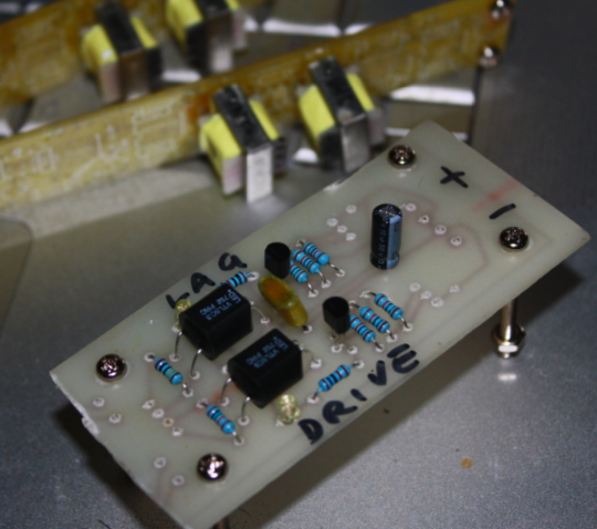
i have tested the circuits on breadboard and i used that to make my vactrol mod pcb
im just curious how to interface it up to pots with the wiring style in the schematic above
_________________
problemchild
melbourne australia
http://cycleofproblems.blogspot.com/
http://www.last.fm/user/prblmchild |
|
|
Back to top
|
|
|
diablojoy

Joined: Sep 07, 2008
Posts: 809
Location: melbourne australia
Audio files: 11
|
| Posted: Sun Oct 25, 2009 2:18 pm Post subject:
|
|
|
hi luka
i recently did some experiments along these lines
for a WSG for all the oscillator pots plus the freq pot and the supply power
the vactrols were all wired in parallel with those pots and in series with the positive power rail which worked ok those are all 1 meg pots so some small limitation on pot range is to be expected
I used VTL3 and from memory , so don't take this as verbatim ,the vactrol resistance was approx 3 meg when dark dropping to roughly 100 ohms when fully on, so in theory 3 meg in parallel with a 100k pot should give a better result. if you want to do this as per a voltage divder you would need to use 2 vactrols or say a VTL3/2, one of the ones with 2 resistive elements , just put all 3 leads in parallel with the 3 pins of the pot.
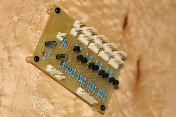
ray wilson recently posted another cct on his site using transistors [look in WSG mods ] which i am trying out now, I have designed and made a board, just haven't finished testing it yet. this is so i can retrieve the 8 vactrols for other experiments.
cheers 
Denis. |
|
|
Back to top
|
|
|
DGTom

Joined: Dec 08, 2008
Posts: 211
Location: Adelaide
Audio files: 3
G2 patch files: 1
|
| Posted: Sun Oct 25, 2009 6:34 pm Post subject:
|
|
|
I assumed thats what the 3 pinned vactrols where for? direct replacements for pots? So the V2R cct. replaces the pot. I'm prob. wrong tho, you know what they say about assumptions  |
|
|
Back to top
|
|
|
Luka
Joined: Jun 29, 2007
Posts: 1003
Location: Melb.
|
| Posted: Sun Oct 25, 2009 7:10 pm Post subject:
|
|
|
if i understand how a pot works correctly, i might be wrong, would the top half of the pot resistnace works in the opposite way to the bottom half, ie as the resistance increases from the bottom wiper to the centre wiper, it decreases witin the centre wiper to the top wiper section
i dont see how a dual vactrol can simulate this, my original guess on this topic was perhaps i could add make a traditional divider layout and use the vactrol to control the bottom resistor.
btw, is that setup actually a divider? i notice that the top wiper doesnt link to anything.
can i just hook the vactrol to the pcb pads for the bottom wiper and center wiper in a traditional vactrol way?
_________________
problemchild
melbourne australia
http://cycleofproblems.blogspot.com/
http://www.last.fm/user/prblmchild |
|
|
Back to top
|
|
|
diablojoy
Joined: Sep 07, 2008
Posts: 809
Location: melbourne australia
Audio files: 11
|
| Posted: Sun Oct 25, 2009 9:34 pm Post subject:
|
|
|
sorry luka as far as i can see the only way of using these as voltage dividers is to use 2 vactrols and control them so one is dark when the other is light
would be difficult to get them to pan exactly right
the required circuitry is beyond me at the moment maybe someone else here has looked into more thoroughly but from your first cct it does not appear you would need that functionality it looks like you only need to go in parallel with the wiper and pin 1 or 3 of the pot |
|
|
Back to top
|
|
|
Luka
Joined: Jun 29, 2007
Posts: 1003
Location: Melb.
|
|
|
Back to top
|
|
|
Mooger5
Joined: May 02, 2007
Posts: 199
Location: Portugal
Audio files: 8
|
| Posted: Sun Oct 25, 2009 10:50 pm Post subject:
|
|
|
I think it´s possible by splitting the CV into non-inverting and inverting signals. With one vactrol receiving an increase in voltage the other receives a decreasing one.
http://www.geofex.com/Article_Folders/VCA%20Applications.pdf see application number 3 and link them like this (not tested):

Blocks A and B are meant to be VCAs but I think it should work with vactrols too. |
|
|
Back to top
|
|
|
diablojoy
Joined: Sep 07, 2008
Posts: 809
Location: melbourne australia
Audio files: 11
|
| Posted: Mon Oct 26, 2009 5:41 pm Post subject:
|
|
|
yes but only sort of
vactrol response is not linear
which would need to be taken into account
to emulate a pot as a voltage divider
It becomes quite complex in semi on states [very small voltage changes=large resistance variations and logrithmic to boot] and
to add to that the attack and decay times are also very different
from each other.
i see no easy way to achieve this but maybe i am over complicating
things ? anyone ?
denis |
|
|
Back to top
|
|
|
Adam-V

Joined: Jan 29, 2007
Posts: 300
Location: Australia
Audio files: 1
|
| Posted: Mon Oct 26, 2009 8:04 pm Post subject:
|
|
|
Luke,
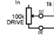
In the drive section the grinder circuit, I think you can just put the vactrol across the DE and DC connections as the pot is merely acting as a variable resistance rather than a divider at that point (Only one side and the wiper are connected). You could put the vactrol in parallel (depending on it's resistive value) and normalise it's control such that it is a maximum resistance when there is not CV present.
Cheers,
Adam-V
_________________
Digitalis Effect | Fractured Symmetry (www.spiralsect.com) |
|
|
Back to top
|
|
|
diablojoy
Joined: Sep 07, 2008
Posts: 809
Location: melbourne australia
Audio files: 11
|
| Posted: Tue Oct 27, 2009 1:47 am Post subject:
|
|
|
luka what cct are you using to drive the vactrol ?
when i did my experiments i borrowed a section from scott's
mutant vactrol filter which did an admirable job |
|
|
Back to top
|
|
|
Luka
Joined: Jun 29, 2007
Posts: 1003
Location: Melb.
|
|
|
Back to top
|
|
|
DGTom
Joined: Dec 08, 2008
Posts: 211
Location: Adelaide
Audio files: 3
G2 patch files: 1
|
| Posted: Tue Oct 27, 2009 3:45 pm Post subject:
|
|
|
 Would love to hear it in action once its up & running, VC Grinder is gonna be gnarly!! Would love to hear it in action once its up & running, VC Grinder is gonna be gnarly!! |
|
|
Back to top
|
|
|
diablojoy
Joined: Sep 07, 2008
Posts: 809
Location: melbourne australia
Audio files: 11
|
|
|
Back to top
|
|
|
diablojoy
Joined: Sep 07, 2008
Posts: 809
Location: melbourne australia
Audio files: 11
|
|
|
Back to top
|
|
|
Luka
Joined: Jun 29, 2007
Posts: 1003
Location: Melb.
|
|
|
Back to top
|
|
|
diablojoy
Joined: Sep 07, 2008
Posts: 809
Location: melbourne australia
Audio files: 11
|
| Posted: Wed Oct 28, 2009 2:22 am Post subject:
|
|
|
not off hand but its just on the MFOS site under WSG mods
easy to find. by the way still haven't got to test that board yet,
been too busy, hopefully will get to it this weekend |
|
|
Back to top
|
|
|
Luka
Joined: Jun 29, 2007
Posts: 1003
Location: Melb.
|
|
|
Back to top
|
|
|
Adam-V
Joined: Jan 29, 2007
Posts: 300
Location: Australia
Audio files: 1
|
| Posted: Wed Oct 28, 2009 7:06 pm Post subject:
|
|
|
How did you end up wiring it in?
Cheers,
Adam-V
_________________
Digitalis Effect | Fractured Symmetry (www.spiralsect.com) |
|
|
Back to top
|
|
|
Luka
Joined: Jun 29, 2007
Posts: 1003
Location: Melb.
|
| Posted: Thu Oct 29, 2009 2:29 pm Post subject:
|
|
|
i connected the vactrol out to the dc / de
i replaced the original grinder and drive pots with voltage offset pots which control the vactrol circuit
the limiting resister on the vactrols mimics the grinder and drive pot values
i could possibly somehow tune the responce of the vactrol a little, the grinder and drive responce range is all bunched up to one side of the input voltage range. it works well enough at this stage
does anyone know how to do this?
_________________
problemchild
melbourne australia
http://cycleofproblems.blogspot.com/
http://www.last.fm/user/prblmchild |
|
|
Back to top
|
|
|
diablojoy
Joined: Sep 07, 2008
Posts: 809
Location: melbourne australia
Audio files: 11
|
| Posted: Fri Oct 30, 2009 2:25 am Post subject:
|
|
|
you could try a 1 or 2k trimmer + a 1k resistor to ground before the base of the 2n3904 in the schematic you were using
that may give you some ability to tweak the response a bit i think maybe.
will drop some of the cv to ground which should increase the range before the led in the vactrol switches hard on .which at a guess is what is happening if it bunches up at the low end .
not quite sure if iam understanding this properly though, the cct i used is a bit different |
|
|
Back to top
|
|
|
The Bad Producer
Joined: Mar 08, 2009
Posts: 282
Location: The Manhole
|
| Posted: Sat Oct 31, 2009 5:30 am Post subject:
|
|
|
This is very interesting...
I'm just wondering if you could use two of those 2N5457 FET circuits from the MFOS site to replace a voltage dividing pot by inverting the CV to one of the FETs. I'd really like to add voltage control to a few boards (like the JH Solina) which have voltage dividing pots, and the vactrol solution eludes me for the time being... also 2N5457s are sooooooo much cheaper and easier to get hold of (for me) than vactrols, even with the cost of adding a little inverter circuit too...
Does anyone have any thoughts on this, before I start to breadboard?
This Vishay doc is fairly interesting, I've not finished examining it yet...
http://www.vishay.com/docs/70598/70598.pdf
also and this mentions that FETs can be used in audio applications (low distortion)...:
http://freespace.virgin.net/ljmayes.mal/comp/vcr.htm
Charlie
_________________
http://loudestwarning.tumblr.com/ |
|
|
Back to top
|
|
|
|

 Forum index » DIY Hardware and Software