| Author |
Message |
joshco
Joined: Nov 14, 2008
Posts: 55
Location: germany
|
 Posted: Sun Oct 25, 2009 4:05 am Post subject:
AC DC VCA Quick question Posted: Sun Oct 25, 2009 4:05 am Post subject:
AC DC VCA Quick question |
  |
|
Hello,
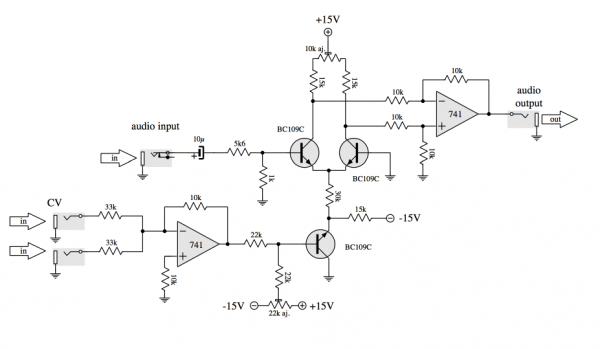
Currently I´m building some VCA´s, theres a DC and a AC Version.
What does this mean in general, are there any differences in sound or in amplification?
Thanks
best regards |
|
|
Back to top
|
|
 |
yusynth

Joined: Nov 24, 2005
Posts: 1314
Location: France
|
| Posted: Sun Oct 25, 2009 7:56 am Post subject:
|
|
|
The AC version is solely dedicated to process audio signals that's why there are capacitors in series with the INPUTS. These capacitors are there to filter out any DC component.
The DC version is more versatile because it can be used for processing either CVs or audio signals.
_________________
Yves |
|
|
Back to top
|
|
|
joshco
Joined: Nov 14, 2008
Posts: 55
Location: germany
|
| Posted: Sun Oct 25, 2009 11:09 am Post subject:
|
|
|
Allright, the caps remove the dc signal in the audio material, whereas the DC version is able to amplify DC signals too.
Thank you! |
|
|
Back to top
|
|
|
robboten
Joined: Nov 26, 2009
Posts: 36
Location: stockholm, sweden
|
| Posted: Mon Feb 25, 2013 7:07 am Post subject:
|
|
|
| In the schematic for the simple VCA module there are two stars at the LED and the circuit around it. Does that mean that the LED only works with the AC version? That could explain why I get no light... And if so, is it possible to have light with the DC version as well? |
|
|
Back to top
|
|
|
yusynth
Joined: Nov 24, 2005
Posts: 1314
Location: France
|
| Posted: Tue Feb 26, 2013 5:15 am Post subject:
|
|
|
If you have installed all these optional components and use it in DC mode then the LED can bright but only for a negative input voltage. The LED circuit was designed for AC only as indicated.
_________________
Yves |
|
|
Back to top
|
|
|
robboten
Joined: Nov 26, 2009
Posts: 36
Location: stockholm, sweden
|
| Posted: Tue Feb 26, 2013 5:23 am Post subject:
|
|
|
Ah, I see. Thank you for your reply!
And also a big <3 for all your work on the modules you have published! I just love everything about them! The clearness of the pictures, the easy to follow schematics, the pcb-layouts and the functions. For me as a noob on the field this has helped me understand so much! Build my fourth module today (Noise, VCA, ADSR, S&H) and is so happy about it all! Next up is a mixer or the Steiner VCF. Probably ending up with all of them sooner or later... it's so much fun! So thank you again so much! |
|
|
Back to top
|
|
|
dancelwerk
Joined: Aug 28, 2009
Posts: 93
Location: berlin
Audio files: 2
|
| Posted: Mon Aug 17, 2015 9:02 am Post subject:
|
|
|
Hi to all, I want to build the DC version but I have no clear what components I have to remove,
is * for the components AC and ** for the DC or viceversa?
I want to say, if I build the DC version, should i be remove Q4, D1, and C3 and C4?
thanks in advance.
Fernando. |
|
|
Back to top
|
|
|
alanwilder81
Joined: Sep 03, 2016
Posts: 310
Location: italy
|
| Posted: Mon Sep 05, 2016 8:41 am Post subject:
|
|
|
Hi all,
a big thanks to Yves Usson for delivering us such amazing material and schematics. i am trying to build my own synth, and i have a couple of questions regarding the student project supervised by T. Rochebois : building a small analogue synth
http://yusynth.net/index_en.php?&arg=1
has any of you ever built that nice CV GATE TRIGGER keyboard controller?
it looks amazingly simple and low components count.
if Yves or anyone else may give me a help, it would be greatly appreciated.
cheers  |
|
|
Back to top
|
|
|
yusynth
Joined: Nov 24, 2005
Posts: 1314
Location: France
|
| Posted: Tue Sep 06, 2016 1:22 am Post subject:
|
|
|
Hi
No I haven't built it, but it was a student project that was successfully completed and the schematics published by Thierry were all tested therefore I guess you may be pretty confident in these. I see no flaw in them.
_________________
Yves |
|
|
Back to top
|
|
|
alanwilder81
Joined: Sep 03, 2016
Posts: 310
Location: italy
|
|
|
Back to top
|
|
|
yusynth
Joined: Nov 24, 2005
Posts: 1314
Location: France
|
| Posted: Sat Oct 08, 2016 1:23 am Post subject:
|
|
|
Either you didn't match the transistors of the differential pair or you did not adjust the trimmer correctly. Also you should use 1% tolerance for the resistors auround the second 741.
_________________
Yves |
|
|
Back to top
|
|
|
|

 Forum index » DIY Hardware and Software » YuSynth