| Author |
Message |
Skrog Productions

Joined: Jan 07, 2009
Posts: 1220
Location: Scottish Borders
Audio files: 159
|
|
|
Back to top
|
|
 |
ashleym
Joined: Aug 20, 2009
Posts: 181
Location: uk
|
 Posted: Thu Jul 05, 2012 1:17 pm Post subject: Posted: Thu Jul 05, 2012 1:17 pm Post subject:
|
  |
|
As ever a great looking panel and I am sure it will make your music that much more........ 
If I could offer an idea or two? On my sequencer I have added a selectable voltage for the CV output. If I want full control of, say, filter cut off I can use the high voltage, CV of pitch- medium voltage range something like 0-5v etc. I know you can use an attenuator, I just prefer switchable ranges.
Secondly I have taken an alternative gate/trigger out. If I switch a step "off" I just route it to another set of outputs. Waste no want not.
Last edited by ashleym on Thu Jul 05, 2012 1:25 pm; edited 1 time in total |
|
|
Back to top
|
|
|
Skrog Productions
Joined: Jan 07, 2009
Posts: 1220
Location: Scottish Borders
Audio files: 159
|
| Posted: Thu Jul 05, 2012 1:23 pm Post subject:
|
|
|
thanks Ashleym , i think this will take most of the autumn to build , i've still an idea or 2 for that blank space on the right , cool idea for a 2 way switch routing the gate .
Dave |
|
|
Back to top
|
|
|
ashleym
Joined: Aug 20, 2009
Posts: 181
Location: uk
|
| Posted: Thu Jul 05, 2012 1:35 pm Post subject:
|
|
|
Dave- the least I could do. I used double pole switches and ran the second output off the second pole.
Ray also does a board for something similar with the 16 Step Sequencer Auxiliary GATE/LED Driver PCB that he's made for the variable step seq you are building. |
|
|
Back to top
|
|
|
diablojoy

Joined: Sep 07, 2008
Posts: 809
Location: melbourne australia
Audio files: 11
|
| Posted: Thu Jul 05, 2012 8:36 pm Post subject:
|
|
|
nice panel  I like how you have saved some width with the offset vertical spacing I like how you have saved some width with the offset vertical spacing
one of rays quantizers in that
space to the lower right might be nice.
_________________
In an infinite universe one might very well
ask where the hell am I
oh yeah thats right the land of OZ
as good an answer as any |
|
|
Back to top
|
|
|
Skrog Productions
Joined: Jan 07, 2009
Posts: 1220
Location: Scottish Borders
Audio files: 159
|
| Posted: Mon Jul 09, 2012 10:54 am Post subject:
|
|
|
Thanks Diablojoy , i have 2 of Rays quantisers im thinking of re-housing soon heh.
Dave |
|
|
Back to top
|
|
|
Skrog Productions
Joined: Jan 07, 2009
Posts: 1220
Location: Scottish Borders
Audio files: 159
|
|
|
Back to top
|
|
|
Skrog Productions
Joined: Jan 07, 2009
Posts: 1220
Location: Scottish Borders
Audio files: 159
|
|
|
Back to top
|
|
|
Skrog Productions
Joined: Jan 07, 2009
Posts: 1220
Location: Scottish Borders
Audio files: 159
|
|
|
Back to top
|
|
|
ashleym
Joined: Aug 20, 2009
Posts: 181
Location: uk
|
| Posted: Tue Aug 21, 2012 1:26 pm Post subject:
|
|
|
16 of those will be fun to solder up  |
|
|
Back to top
|
|
|
Skrog Productions
Joined: Jan 07, 2009
Posts: 1220
Location: Scottish Borders
Audio files: 159
|
| Posted: Wed Aug 29, 2012 2:20 pm Post subject:
|
|
|
| ashleym wrote: | | 16 of those will be fun to solder up |
heh , and sure to cause a burnt finger or 2  |
|
|
Back to top
|
|
|
Skrog Productions
Joined: Jan 07, 2009
Posts: 1220
Location: Scottish Borders
Audio files: 159
|
|
|
Back to top
|
|
|
-minus-
Joined: Oct 26, 2008
Posts: 787
Audio files: 13
|
| Posted: Wed Aug 29, 2012 3:36 pm Post subject:
|
|
|
Dave, are you drilling then stickering.... or stickering then drilling? I'm looking to get some stickers done at the local sign shop and wondering what the best method is.
thanks! |
|
|
Back to top
|
|
|
Skrog Productions
Joined: Jan 07, 2009
Posts: 1220
Location: Scottish Borders
Audio files: 159
|
| Posted: Wed Aug 29, 2012 11:12 pm Post subject:
|
|
|
Hi Minus.
Both , i got a cheap black & white print for drill template , peeled that off then applied the "toner hungry blue" one lined up over the holes.
To move the sticker around easily, put a small amount of washing up liquid into a sink of water and swish to make soapy bubbles , dab the bubbles, with a sponge, onto the adhesive side of the vinyl to de-activate the stickyness .
Leave to dry for a day or so , any defiant airpockets can be lanced with a scalpel blade. After 3 days of evaporation, the sticker is going nowhere.
Good luck
Dave. |
|
|
Back to top
|
|
|
-minus-
Joined: Oct 26, 2008
Posts: 787
Audio files: 13
|
| Posted: Thu Aug 30, 2012 3:17 am Post subject:
|
|
|
Hang on Dave  .... Let me get this right... You are drilling the holes using a separate print out, then stickering the toner hungry blue version? Does this mean you are cutting the blue sticker, around the pre-drilled holes with a scalpel or something? .... Let me get this right... You are drilling the holes using a separate print out, then stickering the toner hungry blue version? Does this mean you are cutting the blue sticker, around the pre-drilled holes with a scalpel or something?
I was going to paper print a drill template and tape or glue stick it to the aluminium panel, drill, then sticker and cut around the holes. I was worried the drill bit might rip the vinyl sticker material. I have used plotter cut vinyl lettering with signs in the past. I used an atomiser spray bottle to soak the sticky side... then move it around... and squeegee in place.
I have found a local sign shop to do the stickers at a reasonable price .
Oh, one other thing... You are not wrapping your sticker around the edges of your panels are you? I was wondering if the corners might lift over time.
Thanks for your help! |
|
|
Back to top
|
|
|
Skrog Productions
Joined: Jan 07, 2009
Posts: 1220
Location: Scottish Borders
Audio files: 159
|
| Posted: Thu Aug 30, 2012 5:55 am Post subject:
|
|
|
| -minus- wrote: | | Does this mean you are cutting the blue sticker, around the pre-drilled holes with a scalpel or something? |
Yes , when the good sticker is on you can turn the panel round and look from the back through the drill holes in daylight and see if those cross-hairs are all in line , after its dry slice em out with a blade.
| -minus- wrote: | | Oh, one other thing... You are not wrapping your sticker around the edges of your panels are you? I was wondering if the corners might lift over time |
mine don't noticably lift , it usually a dirty finger mark or grime that prevents them from sticking (clean corners with vinegar or solvent before pressing down).
If they do misbehave and cause sleepless nights, a dab of glue will sort em .
My local sign shop charges about £25.00 a square meter of print , those big toner cartridges cost a lot , especially when i use his blue all the time heheheheh .
Dave. |
|
|
Back to top
|
|
|
delayed
Joined: Jun 24, 2008
Posts: 130
Location: TN
|
| Posted: Fri Sep 14, 2012 12:35 am Post subject:
|
|
|
| Looking nice |
|
|
Back to top
|
|
|
Skrog Productions
Joined: Jan 07, 2009
Posts: 1220
Location: Scottish Borders
Audio files: 159
|
| Posted: Sun Oct 14, 2012 5:43 am Post subject:
|
|
|
| Thanks , this is taking a bit of planning & time , all worth it in the end |
|
|
Back to top
|
|
|
Skrog Productions
Joined: Jan 07, 2009
Posts: 1220
Location: Scottish Borders
Audio files: 159
|
|
|
Back to top
|
|
|
ashleym
Joined: Aug 20, 2009
Posts: 181
Location: uk
|
| Posted: Sun Oct 14, 2012 12:49 pm Post subject:
|
|
|
Keep the faith. You will finish. You will finish........
My building has stopped since I have made a little more commitment to making music, so I am jealous that you manage to do both 
_________________
http://soundcloud.com/for-mash-get-ash |
|
|
Back to top
|
|
|
dancelwerk
Joined: Aug 28, 2009
Posts: 93
Location: berlin
Audio files: 2
|
| Posted: Tue Oct 16, 2012 7:40 am Post subject:
|
|
|
Hi to all i want to know if i can use a normal electrolitic capacitor for the variclock sequencer instead of one tantalum capacitor of the project, i cant get polarized tantalum capacitors here where i live.
thanks in advance. |
|
|
Back to top
|
|
|
Skrog Productions
Joined: Jan 07, 2009
Posts: 1220
Location: Scottish Borders
Audio files: 159
|
| Posted: Tue Oct 16, 2012 11:47 am Post subject:
|
|
|
| Hi , i would think an electrolytic would be ok but im not sure , someone will know |
|
|
Back to top
|
|
|
Skrog Productions
Joined: Jan 07, 2009
Posts: 1220
Location: Scottish Borders
Audio files: 159
|
| Posted: Tue Oct 16, 2012 11:55 am Post subject:
|
|
|
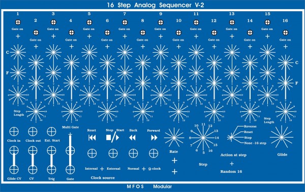
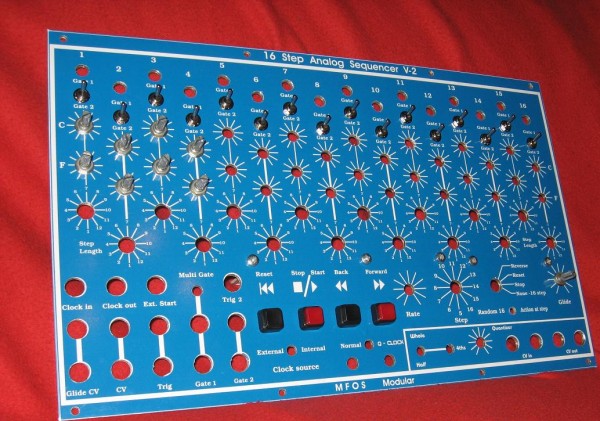
Almost there now , wired up , quick test and found some pots working back to front , heh , those to sort & tidy the cables up with some ties , i'll give it a good test at the weekend when i screw it back into the modular (there has been a draughty space in the modular for 3 months )
A pic of the back end and a couple of the front , i'm taking a wee rest from synth wiring for a few weeks after it's all working
Dave.
| Description: |
|
| Filesize: |
242.68 KB |
| Viewed: |
681 Time(s) |
| This image has been reduced to fit the page. Click on it to enlarge. |

|
| Description: |
|
| Filesize: |
185.29 KB |
| Viewed: |
732 Time(s) |
| This image has been reduced to fit the page. Click on it to enlarge. |

|
| Description: |
|
| Filesize: |
314.15 KB |
| Viewed: |
659 Time(s) |
| This image has been reduced to fit the page. Click on it to enlarge. |

|
|
|
|
Back to top
|
|
|
ashleym
Joined: Aug 20, 2009
Posts: 181
Location: uk
|
|
|
Back to top
|
|
|
diablojoy
Joined: Sep 07, 2008
Posts: 809
Location: melbourne australia
Audio files: 11
|
| Posted: Wed Oct 17, 2012 9:22 pm Post subject:
|
|
|
Hi Dave
build is looking good
quick question
what is the overall size of your panel ?
I have 2 to do on my list and with a feature set exactly the same as your build so your panel layout looks like a good point to work from.
_________________
In an infinite universe one might very well
ask where the hell am I
oh yeah thats right the land of OZ
as good an answer as any |
|
|
Back to top
|
|
|
|

 Forum index » DIY Hardware and Software » MusicFromOuterSpace.com designs by Ray Wilson


 when soldering those 16 rotary sw's & resistors (the thought of it after work