| Author |
Message |
ericcoleridge

Joined: Jan 16, 2007
Posts: 889
Location: NYC
|
 Posted: Thu Jul 10, 2008 1:36 pm Post subject:
Help, Please, Wiring up Topp's Buchla 281 Function Generator Posted: Thu Jul 10, 2008 1:36 pm Post subject:
Help, Please, Wiring up Topp's Buchla 281 Function Generator
Subject description: Free Function Gen Pic!! plus: i don't quite understand the switch wiring |
  |
|
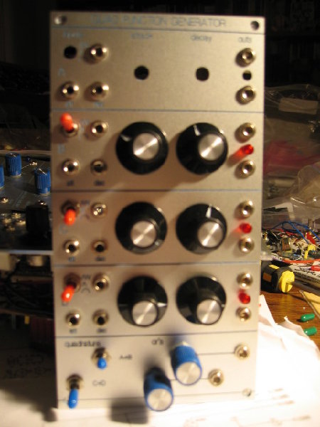
Ok, so, I have my boards assembled, and I've followed the wiring suggestion for the Attach, Decay, and 10V, all as illustrated in the PDF. I also follow the inter-board wiring.
However, I have no wiring example for the SPDT switch... and I'm not really understanding the schematic either. The PDF doesn't seem to be up anywhere anymore, so it's not in front of me as I write this, but the way I remember it, there are 4 wires connecting to the switch-- but aren't there only 3 tabs on an SPDT?
There's the gate input, transient, cycle, and "ms" out.
Obviously, I'm no electronic engineer, and frankly, I'm probably not too bright in general-- so can anyone help me here?
Also, if there's anything else confusing that's not specifically addressed in the PDF, I could use a heads up. pretty please?
I looked through the earlier post, but it's like 20 pages long now and impossible to find anything.
| Description: |
|
| Filesize: |
85.5 KB |
| Viewed: |
338 Time(s) |
| This image has been reduced to fit the page. Click on it to enlarge. |
|
|
|
|
Back to top
|
|
 |
Ilanode
Joined: Sep 14, 2007
Posts: 80
Location: Berlin/FRG
|
| Posted: Thu Jul 10, 2008 2:13 pm Post subject:
|
|
|
| It's true just 3 tabs but 4 wires! And 1 diode as well! Just send me a PM with your email I I'll send you the doc. |
|
|
Back to top
|
|
|
blue hell
Site Admin

Joined: Apr 03, 2004
Posts: 24456
Location: The Netherlands, Enschede
Audio files: 297
G2 patch files: 320
|
| Posted: Thu Jul 10, 2008 2:22 pm Post subject:
|
|
|
| Ilanode wrote: | | Just send me a PM with your email I I'll send you the doc. |
Hint: you can attach documents to PMs as well, as long as it's not bigger than about 10MB or so.
_________________
Jan
also .. could someone please turn down the thermostat a bit.
 |
|
|
Back to top
|
|
|
ericcoleridge
Joined: Jan 16, 2007
Posts: 889
Location: NYC
|
| Posted: Thu Jul 10, 2008 2:24 pm Post subject:
|
|
|
Thanks Ilanode! I PMed you.
Feel free, anyone, to drop some knowledge here too. Probably this question could come up again, I guess, or it might just be me.  |
|
|
Back to top
|
|
|
ericcoleridge
Joined: Jan 16, 2007
Posts: 889
Location: NYC
|
| Posted: Thu Jul 10, 2008 2:40 pm Post subject:
|
|
|
I got it.
I didn't realize that this was part of the original build doc PDF. I must have just missed it somehow. Got it now. Thanks again |
|
|
Back to top
|
|
|
numbernone
Joined: Aug 16, 2006
Posts: 477
Location: new york city
|
| Posted: Thu Jul 10, 2008 2:48 pm Post subject:
|
|
|
As always I am SO glad others are taking the plunge and guinea pigging all these great designs before I even dip my toes. I have 10 of the boards waiting and I havent even looked at any of the docs yet. I just KNOW that I could not pass up the opportunity for at least 2 full banks of these guys.
Best luck Eric, let us all know how it turns out. |
|
|
Back to top
|
|
|
Ilanode
Joined: Sep 14, 2007
Posts: 80
Location: Berlin/FRG
|
| Posted: Thu Jul 10, 2008 2:52 pm Post subject:
|
|
|
| Blue Hell wrote: | | Hint: you can attach documents to PMs as well, as long as it's not bigger than about 10MB or so. |
It's my text blindness. Just had another look and found the option to "Add an Attachment". |
|
|
Back to top
|
|
|
toppobrillo

Joined: Dec 10, 2005
Posts: 766
Location: oakland, ca
G2 patch files: 1
|
|
|
Back to top
|
|
|
ericcoleridge
Joined: Jan 16, 2007
Posts: 889
Location: NYC
|
| Posted: Thu Jul 10, 2008 11:06 pm Post subject:
|
|
|
OK, thanks again everyone.
But one other thing; I accidentally assembled the 'peak' circuitry on my 'A' boards. Will it be a problem for me to go ahead and use it as such? Or is it irrelevant which board it's on? |
|
|
Back to top
|
|
|
Pehr

Joined: Aug 14, 2005
Posts: 1307
Location: Björkvik, Sweden
Audio files: 2
|
|
|
Back to top
|
|
|
|

 Forum index » DIY Hardware and Software

