Joined: Jan 14, 2010 Posts: 5881 Location: Moon Base
Audio files: 709
Posted: Sat Apr 04, 2015 4:56 pm Post subject:
NANDulator Subject description: single NAND chip noise machine
I was wondering if I could use a NAND gate to make 2 oscillators since it has 2 inputs. So I did some experiments
and ended up with the circuit build around U1c/U1d. By itself it can produce modulated sounds, PWM and a sort
of a stepped APC like sound. I didn't want to waste the other 3 gates so I made another one of those circuits,
mixed them together with a 3rd NAND and used the output to modulate another oscillator. resulting in
The NANDulator
I recorded a quick demo which has the NANDulator with some reverb. I'm using trimpots at the moment and I think the 500K
is a bit scratchy so it produced a bit of extra weirdness. You should get much better control with real pots.
And as always: experiment!
NOTE: NOT ALL 4093 CHIPS SEEM TO WORK PROPERLY IN THE NANDulator, MORE INFO IN THIS POST!
NANDulator.gif
Description:
NANDulator schematic
Filesize:
19.85 KB
Viewed:
2230 Time(s)
This image has been reduced to fit the page. Click on it to enlarge.
Joined: Jan 14, 2010 Posts: 5881 Location: Moon Base
Audio files: 709
Posted: Sun Apr 05, 2015 11:33 am Post subject:
I'm glad you listened to the whole thing, I was quite surprised when it started doing that.
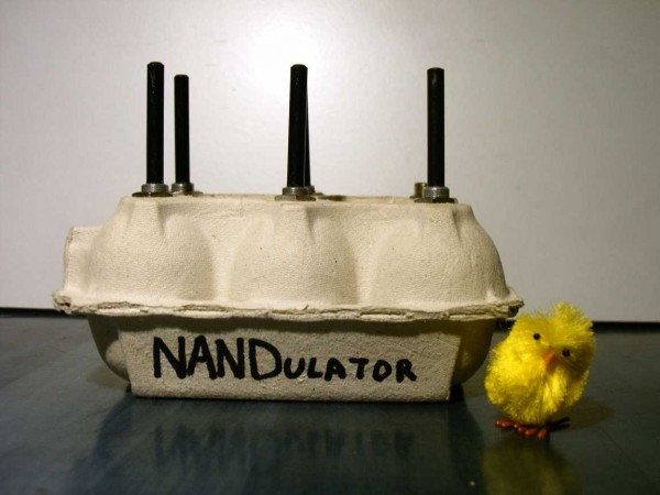
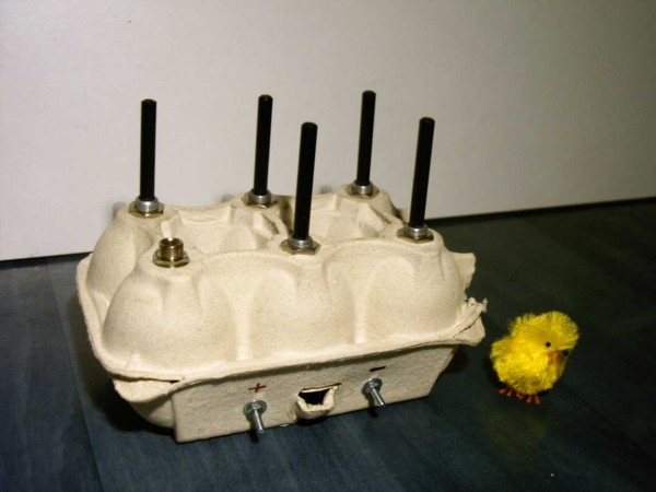
I just put together an easter edition so here are some photos
NANDulator - 01.jpg
Description:
NANDulator
Filesize:
53.83 KB
Viewed:
991 Time(s)
This image has been reduced to fit the page. Click on it to enlarge.
NANDulator - 02.jpg
Description:
NANDulator
Filesize:
53.82 KB
Viewed:
1027 Time(s)
This image has been reduced to fit the page. Click on it to enlarge.
NANDulator - 03.jpg
Description:
NANDulator
Filesize:
47.87 KB
Viewed:
1011 Time(s)
This image has been reduced to fit the page. Click on it to enlarge.
Joined: Jan 14, 2010 Posts: 5881 Location: Moon Base
Audio files: 709
Posted: Tue Apr 07, 2015 8:12 am Post subject:
In that case let's add Atari Punk Console too in case APC isn't enough googlebot food: NANDulator NANDulation NANDulate CD4093 4093 quad NAND CMOS DIY electronic noise drone synth synthesizer box free sex machine _________________ "My perf, it's full of holes!" http://phobos.000space.com/ SoundCloudBandCampMixCloudStickney SynthyardsCaptain ColliderTwitchYouTube Last edited by PHOBoS on Wed Apr 15, 2015 7:13 am; edited 1 time in total
...looked a little prettier without the output cap/potential divider.
Concept - 50mm x 50mm, all components soldered on bottom of board except 5 pots as shown.
It's probably not small enough to fit in an egg, maybe a large goose egg
The pot terminals could fit 0.1" headers for offboard controls.
Back pcb is my layout of Yves Usson's MinMax...
Joined: Jan 14, 2010 Posts: 5881 Location: Moon Base
Audio files: 709
Posted: Tue Apr 07, 2015 2:21 pm Post subject:
that's NANDtastic, and very small. well done!
I did test adding diodes to the input pins, well actually I just hooked up my modular lunetta which already has diodes on the outputs,
and that does work. Not really necessary to add that to the PCB though, you can easily solder some wires to it and add the diodes to
whatever connectors you want to use. you could even use a switch to choose between the direction of the diodes. _________________ "My perf, it's full of holes!" http://phobos.000space.com/ SoundCloudBandCampMixCloudStickney SynthyardsCaptain ColliderTwitchYouTube
On next morning viewing, I'm wondering if it would be better to relocate the out/power pins and stick an attenuator there(centre back); if you made multiple instances of the NANDulator it may be musically useful to have an onboard fade. Maybe a second out for headphone monitoring as you mix the NANDulators.
I'd like to see the interactions on oscilloscope(s) to understand the potential of the diode inputs and also what the NANDulator can do in the timing domain rather than the audio domain. Switches...maybe croc pins or bananas. I take it the diode inputs are digital and not analogue sensitive in any way?
Joined: Jan 14, 2010 Posts: 5881 Location: Moon Base
Audio files: 709
Posted: Wed Apr 08, 2015 1:13 pm Post subject:
an attenuator on the output would definetly be useful, if you can fit that on there.
With the diodes you can turn the NAND oscillators on/off. If you would connect
them to pins 8/12 in a way so you could force them high (cathodes connected
to the nand pins) they turn into standard oscillators. Or if you connect the diodes
the other way around you can turn them off. you could connect them to all input pins.
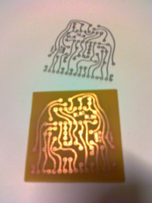
Here is an attempt for a single sided PCB layout for the NANDulator (we might have a go at it with our DIY workshop). Proudly made with my little hands and Inkscape (colours and curves were the same price si i used them!)… It's my first time at it, could someone maybe double check? Also please point any other eventual conceptual mis-design. As one can see i put all outboard connectors on one side, having them sorted by pot, i suppose this is ok? Are the traces too thin (they're .02 in wide)? Maybe just make the ground traces thicker? i also put a capacitor between the power rails, i don't know if it's requested for this very design… Oh well so much noobism.
More generally i would also be very grateful to hear of techniques, do/don'ts etc in this matter of PCB layout design, for instance how to make it more compact and such.
nandulayout.jpg
Description:
Beware! Not verified yet! Actually possibly completely wrong!
Filesize:
68.48 KB
Viewed:
945 Time(s)
This image has been reduced to fit the page. Click on it to enlarge.
Joined: Jan 14, 2010 Posts: 5881 Location: Moon Base
Audio files: 709
Posted: Fri Apr 10, 2015 6:58 pm Post subject:
It looks good to me and I love the curvy hand drawn design
If you're not going to use an attenuator on the output add a 10K resistor instead. It works as a voltage divider
together with the 47K resistor to bring the level down. Traces should be wide enough for the (low) current
as long as it doesn't cause any problems with etching. You could make them bigger but keep enough clearance
between the traces and solderpads (to prevent shorts when soldering). I didn't draw a power decoupling
cap but it's a good addition for this circuit. As for making it more compact, with all the pot connections
on one side you'll probably won't get it a lot smaller and a very small PCB is harder to solder anyway. _________________ "My perf, it's full of holes!" http://phobos.000space.com/ SoundCloudBandCampMixCloudStickney SynthyardsCaptain ColliderTwitchYouTube
I breadboarded the NANDulator with 1M pots and uF caps.
Watched it on the 'scope and with a led on the output.
My impression is that the "small instrument live hands-on" approach which you recorded is the best application as it stands. At audio frequencies you can play the changes as such.
At gate rates the knobs have a distinct delay and "conducting a drummer to play an unrelated rhythm and tempo of their choosing" is not really a "playable" option.
Having said that adding voltage control might open up this side of the NANDulator.
Excellent!
It's certainly a work first time design!
I'm currently mulling about a 50x50mm sandwich board layout with pots/mixers on top and headered onto a NANDulator core with optocouplers or jfets (or jumpers for simple application). Top board (jumpered) could be uni or bi-polar.
I see from Royal Mile Research that anti-log pots (or simulated) are the correct resistance curve.
You cannot post new topics in this forum You cannot reply to topics in this forum You cannot edit your posts in this forum You cannot delete your posts in this forum You cannot vote in polls in this forum You cannot attach files in this forum You can download files in this forum

 Forum index » DIY Hardware and Software » Lunettas - circuits inspired by Stanley Lunetta